Operation, Card-edge controls and indicators – status led, Card-edge controls and indicators – Grass Valley DDA-1113 User Manual
Page 8: Status led, 3 operation, 1 card-edge controls and indicators – status led
GUIDE TO INSTALLATION AND OPERATION
8 | DDA-1113
The rear panel provides the following connections on BNC connectors:
1 AES-3id input
a passive loop-through only for DDA-1113-DRP/L
4 and up to 9 outputs
3 Operation
3.1 Card-Edge Controls and Indicators
– Status Led
The status monitor LED is located on the front card-edge of the
DDA-1113
, and is visible through the front access door
of the DENSITÉ frame. This multi-color LED indicates the status of the
DDA-1113
by color, and by flashing/steady
illumination.
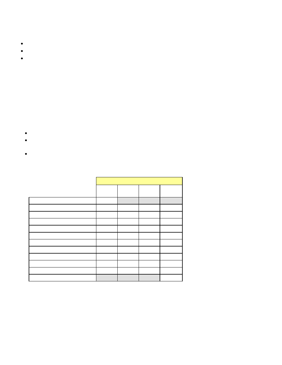
The chart shows how the various error conditions that can be flagged on the
DDA-1113
affect the LED status.
If a cell is gray, the error condition cannot cause the LED to assume that status
If more than one LED status is possible for a particular error condition, the status is configurable.
See Section 3.2.2 for details.
The factory default status is shown by a
The LED will always show the most severe detected error status that it is configured to display, and in the chart error
severity increases from left to right, with green representing no error/disabled, and flashing red the most severe error.
LED Status
Error Condition
Green
Yellow
Red
Flashing
Red
No errors
No input lock
Biphase Coding Error
Parity Error
CRCC Error
Slipped sample
Confidence
Invalid
Non audio
No signal input 1
No signal input 2
Hardware Failure / No Rear
If the LED is Flashing Yellow, it means that the card is selected for local control using the Densité frame’s control
panel. See Section 3.2 for details.