Connection p, Connection p connection ports orts orts orts orts – Grass Valley ADVC-55 User Manual
Page 12
Installation and Operation
In
s
ta
lla
tio
n
a
n
d
O
p
e
ra
tio
n
1
Installation and Operation
12
Connection P
Connection P
Connection P
Connection P
Connection Ports
orts
orts
orts
orts
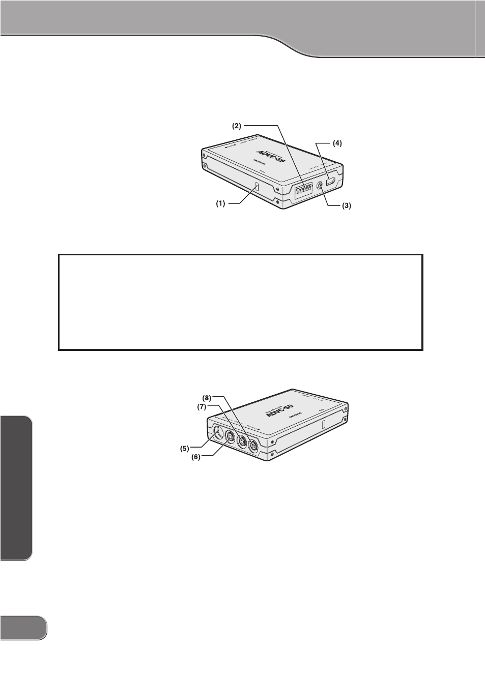
Front/Right-Side
(1) Status Indicator
(2) DIP Switches*
(3) Power Input Jack**
(4) IEEE1394 OUT Port (6-pin)
* : Refer to "Setting DIP Switches" on Page 13.
** : AC adapter is optionally available. (Do not operate with AC adapter other than the provided.)
Left-Side
(5) S-Video IN Port
(6) Video IN Port
(7) Audio (L) IN Port
(8) Audio (R) IN Port
NOTE:
ADVC-55 first detects S-Video input if both S-Video IN and Video IN port are connected
and used at the same time.
Status Indicator
Status indicator shows the present condition of conversion. When it illuminates green, DV stream
output from IEEE1394 port is detected. When it illuminates red;
- ADVC-55 is supplied power from computer.
- ADVC-55 ceases DV stream output receiving a deck-halt command from computer.
- ADVC-55 can not produce normal DV stream output because of excess fluctuations of synchro-
nization signals.
- ADVC-55 detects macrovision signals from video deck.