Status and report – Grass Valley ADA-1033 User Manual
Page 3
ADA-1033
Guide to Installation and Operation
{LEVEL}
Permits the adjustment of the level of channel 1 or 2
separately or simultaneously.
LEVEL
Signal gain can be set from –96 to
+31.5 dB. The default value is 0 dB.
{MONITORING}
Allows the pre-selection of the monitored signal. The
ON/OFF command will come from a monitor module like the
MSB-1121 in slot 20 of the Densité frame.
{CONFIGURE ALARM}
It is possible to associate the STATUS Led colour and/or a
GPI relay activation to each detected error.
Alarm relay activation depends of the ENABLE selection of
the controller board menu GPI REPORT.
ALARM LEVEL
Associates to each error the STATUS
led colour: GREEN, YELLOW, RED
and FLASH RED. This selection has
no influence on the {STATUS} menu
display.
ALARM REPORT
The default value NONE is assigned
to errors. Alarm relay activation will
be associated to an error when GPI is
set.
{FACTORY DEFAUT}
RESTORE
Set the module with the factory default
parameters.
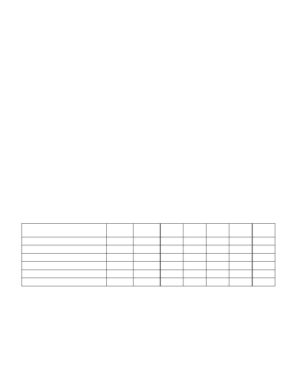
Status and Report
This table shows the front Led colour and the report action according to the level of a given error condition. Notice that the
“Flashing Yellow” indicates that the SELECT button on the front panel has been pushed, and the card is being accessed via
the communication protocol.
Non
requested
GPI
Report
Green Yellow Red
Flashing
Red
Flashing
Yellow.
Overload on Input 1
-
Overload on Input 2
-
No signal detected on Input 1
-
No signal detected on Input 2
-
Card accessed via the communication protocol
- - -
-
-
-
Yes
Rear Panel not matching
-
- - - - Yes -
: Factory default.
Note: The non requested message affectation to an alarm status can only be accessed by the communication protocol (serial
port)