Cabling, Inputs, Outputs – Grass Valley 8964DEC v.1.0.5 User Manual
Page 10: Reference loop-through input
10
8964DEC/-FS Instruction Manual
Installation
Cabling
Cabling to and from the module is done at the back of the Gecko 8900
frame.
Note
At the back of every hard cover manual are overlay cards that can be placed
over the rear connector BNCs to identify the specific 8964DEC connector
functions.
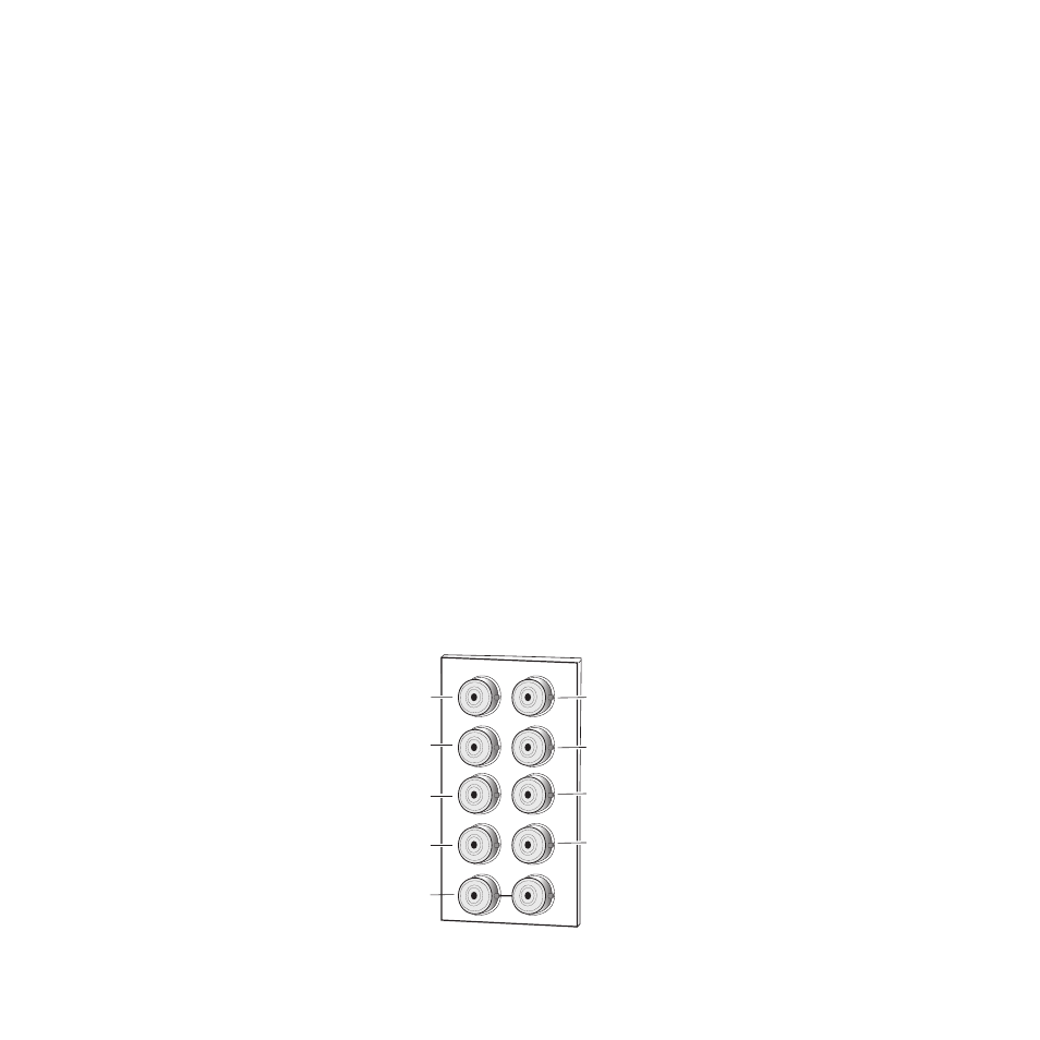
Inputs
Four analog composite video inputs are provided at BNCs J1, J3, J5, and J7.
The inputs are non-looping and internally terminated.
Note
If feeding a monochrome signal to a channel, select
Monochrome In
with the
Composite In controls. Refer to
control summary.
Outputs
Four corresponding serial digital video outputs are provided at BNCs J2,
J4, J6, and J8 as shown in
. There is no audio tracking output on the
output of the module.
Reference Loop-through Input
Connect an NTSC/PAL analog color black reference source to one of the
loop-through reference connectors, J9 or J10. Terminate the unused con-
nector into 75
Ω
if the signal is not looped to other equipment.
Note
The line rate for the module (all four decoder channels) will be auto-detected
from the Reference In signal.
Figure 3. 8960 Input/Output Connectors
J2
J4
J6
J8
J1
J9 J10
IN
X
J3
J5
J7
J2
J4
J6
J8
8208_02
Reference In
(loop-through)
SDI Out 1
CV In 1
CV In 2
CV In 3
CV In 4
SDI Out 2
SDI Out 3
SDI Out 4