Ensemble Designs 5120 Dual Digital Video Distribution Amplifiers User Manual
Page 4
Model 5120/5125 Dual Serial DAs
5120/5125-4
INSTALLATION
Plug the 5120 or 5125 module into any one of the slots in the tray and install the plastic
overlay provided onto the corresponding group of rear BNC connectors associated with the
module location. Note that the plastic overlay has an optional adhesive backing for
securing it to the frame. Use of the adhesive backing is only necessary if you would like
the location to be permanent and is not recommended if you need to change module
locations. This module may be hot-swapped (inserted or removed) without powering down
or disturbing performance of the other modules in the system.
CABLING
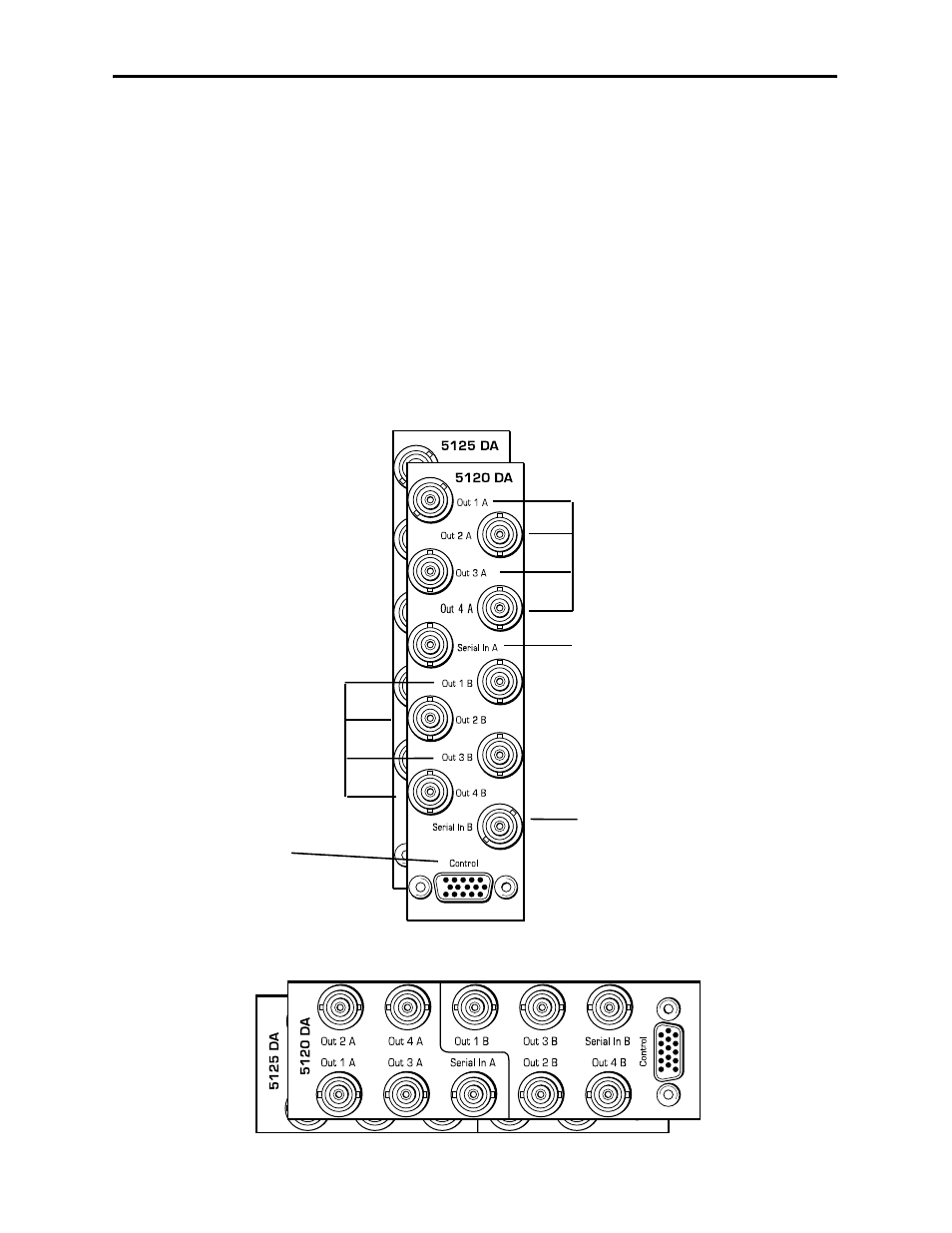
Refer to the 3 RU and 1 RU backplane diagrams of the modules below for cabling instruc-
tions. Note that both modules have identical rear connectors. Unless stated otherwise, the
1 RU cabling explanations are identical to those given in the 3 RU diagram.
Connect one of the serial
digital signals to be distributed
to the Serial In A BNC.
The CONTROL 15-pin
D-connector is not used
in this application.
Connect serial digital output
destinations to the outputs at
BNCs Out 1 A - Out 4 A.
Connect one of the serial
digital signals to be distributed
to the Serial In B BNC.
Connect serial digital output
destinations to the outputs at
BNCs Out 1 B - Out 4 B.
3 RU Backplane
1 RU Backplane