Amer Networks SGD8 User Manual
Page 12
10
I
DENTIFYING
E
XTERNAL
C
OMPONENTS
This chapter describes the front panel, rear panel and LED indicators of the Switch
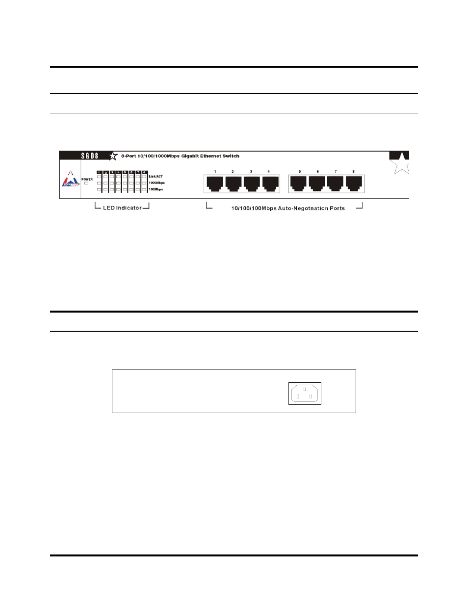
Front Panel
The front panel of the Switch consists of eight 1000BASE-T ports and LED
indicators.
Front panel view of the Switch
z
Eight Gigabit Ethernet ports of 10/100/1000Mbps Auto-Negotiation
interface.
z
Comprehensive LED indicators display the conditions of the Switch and
status of the network. A description of these LED indicators follows (see
LED Indicators).
Rear Panel
The rear panel of the Switch consists of an AC power connector. The following figure
shows the rear panel of the Switch.
Rear panel view of the Switch
z
AC Power Connector This is a three-pronged connector that supports the
power cord. Plug in the female connector of the provided power cord into
this connector, and the male into a power outlet. Supported input voltages
range from 100~240V AC at 50~60 Hz.