Amer Networks SGD5 User Manual
Page 12
12
I
DENTIFYING
E
XT ERNAL
C
OMPONENTS
This chapter describes the front panel, rear panel and LED indicators of the
Switch
Front Panel
The figure below shows the front panels of the switch.
Front panel view of the Switch
LED Indicators
Comprehensive LED indicators display the conditions of the Switch and
status of the network. A description of these LED indicators follows (see LED
Indicators).
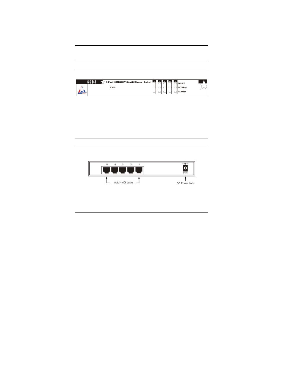
Rear Panel
The rear panel of the Switch consists of an DC power connector. The
following figure shows the rear panel of the Switch.
Rear panel view of the Switch
DC Power Jack: