12 time synchronization – Westermo U200 Operator manal User Manual
Page 33
V4.5
www.westermo.com
U/R/T200 series
- 33 -
12 Time synchronization
Variable latencies through the protocol stacks and the Ethernet switches will degrade the
timing accuracy that can be achieved when time synchronization is performed via a switched
Ethernet infrastructure. Time stamping of incoming and outgoing time packets shall
preferably be done as low as possible in the protocol stack. The Ethernet switch latency
depends on the network load and the switch architecture. This problem is solved by
integrating state of the art time synchronization properties on the T200 switches from
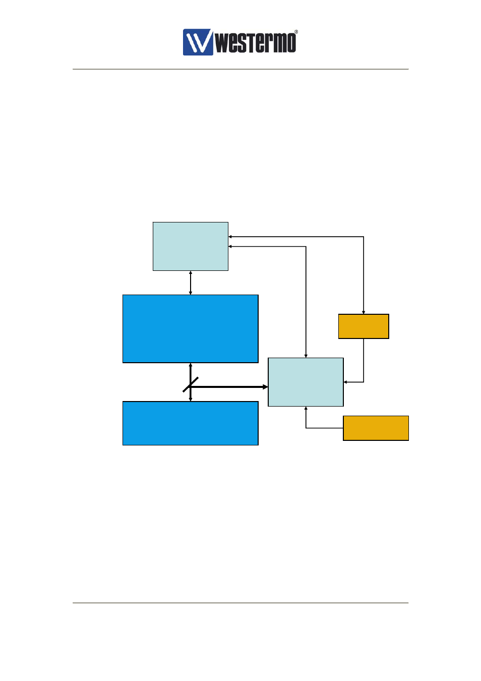
Westermo OnTime. The main building blocks of the Westermo OnTime time server
(SNTP/NTP)/PTP (IEEE1588 v1) implementation (T200) is shown below:
Figure 14, T200 building blocks
Incoming and outgoing time packets are time stamped in hardware at the Media Independent
Interface (MII) between the switch core and the Ethernet PHY. An incoming time packet is
time stamped before it is forwarded through the Ethernet switch core and an outgoing time
packet is time stamped after the packet has been sent through the switch core. This means
that variable latency through the switch core has no impact on the time synchronization
accuracy. Thus, the T200 is network load independent. The time stamping is performed in
an FPGA (Field Programmable Gate Array). The FPGA also generates the local clock of the
PTP clock implementation based on either an external Pulse Per Second (PPS) input from
e.g. a GPS receiver, or only based on a local oscillator (e.g. the switch core oscillator). The
drift and offset of the local oscillator is adjusted based on the PPS signal in case an external
time base is used.
CPU
Switch core
Ethernet PHY
MII/RMII/SMI
FPGA
GPS
PPS
RS422/RS232
Oscillator