Power the unit and connect to network – Westermo MDI-110-F3x User Manual
Page 3
3.1 Connect the PWR1 / PWR2, and the unit will be powered on. PWR1 / PWR2 LED will turn
Blinking to show unit booting up. When the unit is ready, the PWR1 / PWR2 LED turn Green to
show current input.
3.2 Connect the 10/100M Ethernet Port: Connect the network nodes to the MDI series with 4-pair
CAT5 UTP cable. The 10/100M interfaces support auto MDI/MDIX.
3.3 Connect the 100Mbps(MDI-110-F3) /Gigabit (MDI-110-F3G) TX of combo ports: Connect the
network node to the MDI series with 4-pair CAT5 UTP cable. The 100Mbps / Gigabit TX interfaces
support auto MDI/MDIX as well.
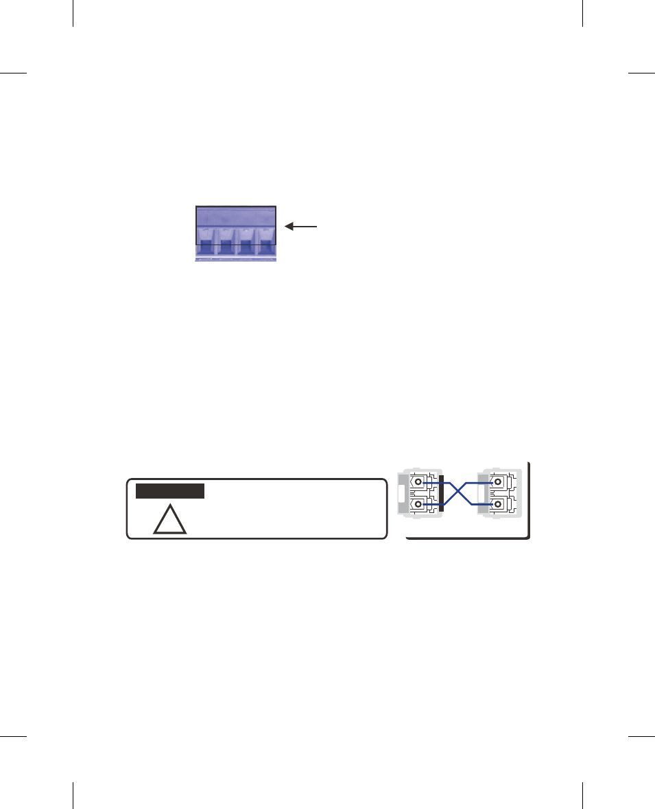
3.4 Connect the SFP transceiver: Plug in SFP fiber transceiver. We recommend using Westermo
certificated SFP mini GBIC transceiver. Cross-connect the transmit channel at each end to the receive
channel at the opposite end as illustrated in the figure below.
V+ V-
V+ V-
Power1
Power2
Accept 12~24AWG wire. The switch
provides auto polarity reverse
Power the unit and connect to network
!
This is a Class 1 Laser/LED product.
Don’t stare at the Laser/LED Beam.
TX
RX
A
B
TX
RX
ATTENTION
3.5 Should you need to connect the Digital Input or Relay Output, please refer to the wiring
method introduced in MDI series Manual.