Multidrop dual channel, y-mode configuration, Prepare the fibre optical network – Westermo ODW-720-F2 User Manual
Page 7
7
6651-2235
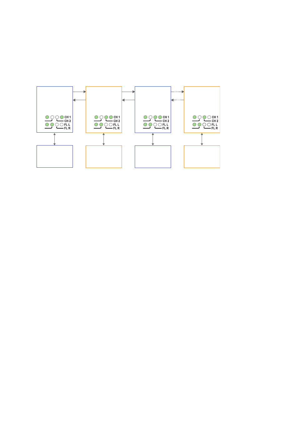
Multidrop dual channel, Y-mode configuration
In dual channel mode it is possible to use two separate data streams in a single ODW-
720 network. However, all ODW-720’s must be set to the same speed and data format.
This, of course, limits the number of possible applications for a dual channel network.
In Y-mode mode an ODW-720 network will behave as a 2-wire bus. I.e. all communica-
tion devices will “hear” the data sent out by other communication devices.
RX2
TX2
End Unit
S2: 3 ON
S2: 4 OFF
S2: 3 OFF
S2: 4 ON
S2: 3 OFF
S2: 4 OFF
End Unit
S1: 3 ON
S2: 4 ON
Device 1
Communicates
with device 3 on the
primary data channel
Device 2
Communicates
with device 4 on the
secondary data channel
Device 3
Communicates
with device 1 on the
primary data channel
Device 4
Communicates
with device 2 on the
secondary data channel
TX1
RX1
RX2
TX2
TX1
RX1
RX2
TX2
RS-232
RS-232
RS-232
Fibre
pair
Fibre
pair
Fibre
pair
RS-232
TX1
RX1
RX2
TX2
TX1
RX1
PWR
FP
TD
RD
PWR
FP
TD
RD
PWR
FP
TD
RD
PWR
FP
TD
RD
Prepare the fibre optical network
• Configure all ODW-720 units for the correct speed and data format using DIP-
switches S1:1 – S1:7. Again, notice that all ODW-720’s must be set to the same
speed and data format.
• The first and last ODW-720 units must be configured as Multidrop end units by
setting DIP-switch S2:3 to the ON position (End units only have one fibre pair
each and must know that this is a fact).
• All ODW-720 units that are to use the primary data channel (“blue” units in the
picture above) must have DIP-switch S2:4 set to the OFF position. Units that are
to use the secondary data channel (“orange” units in the picture above) must have
DIP-switch S2:4 set to the ON position.
• Set DIP-switch S2:6 as desired. See page 33 “Status port” for more information.
• Verify that DIP-switches S1:8, S2:1, S2:2, S2:5 and S2:8 are set in the OFF position.
• Connect the fibre pairs between the units. Always connect CH 1 from one unit to
CH 2 on the next unit as shown in the picture above.
• Connect the power supply to all units and verify that all fibre links become active.
(CH 1 and CH 2 LED’s are on, FL L and FL R LED’s are off).
• Connect the communication devices to the corresponding ODW-720 unit.
• The network is now up and running.
Note: In an ODW-720 fibre optic network there will be some additional processing
delays that do not exist in an electrical bus. It is possible that the application must be
adjusted to accommodate these delays if using many ODW-720 units in a large network.
See page 31 “Calculating system processing delay” for more information on how to
determine the overall system delay time.