General instructions, Binary inputs – WattMaster WCC III part 2 User Manual
Page 6
1. GENERAL INSTRUCTIONS
WCC III Technical Guide
1-4
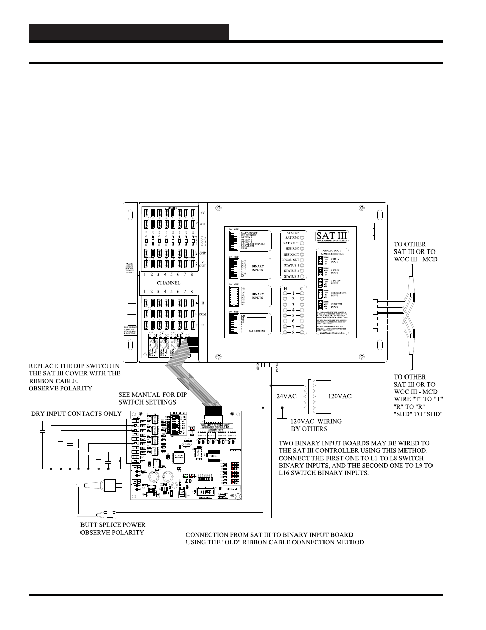
The SAT III controller has two sets of 8 small switches on its front
cover labeled L1-L16.
Switches
L1-L8 are housed together in
one module, and switches L9-L16 are housed together in another
module. One module of switches is removed for each binary input
board and replaced with a ribbon cable which connects the binary
input board to the SAT III controller. The binary devices to be
monitored are then wired to the terminal strip of the binary input
board. The binary input board requires a 24 VAC power supply.
The SAT III can also accept two HSS Binary Input Boards.
Binary Inputs
A binary input is an On/Off (dry contact closure) signal sent to
the SAT III controller to allow monitoring of air fl ow switches,
switch settings, etc. The SAT III controller comes standard with
16 small switches on its front panel labeled, L1-L16 which are in
effect manually controlled binary inputs. The WCC III monitors
the On/Off status of these switches and can control and/or alarm
based on the position of these switches. The binary input board(s)
allow the manual dip switches to be replaced with a terminal strip
which accepts wiring from remote mounted binary input devices.
Binary Inputs