Watson-Marlow 505S User Manual
Page 5
5
The pumphead can be run clockwise for extended tube life, or anti-clockwise to operate against higher pressures.
Flow rates
Flow rates for the 505S were obtained using silicone tubing with the pumphead rotating clockwise, pumping water at 20C with
zero suction and delivery pressures. For critical applications determine flow rates under operating conditions.
Installation
Fit the track in any one of three orientations, over the drive shaft and locating boss. Secure the track with the locating screw.
Ensure the drive shaft is degreased before locating the rotor onto the shaft via the split collet. Tighten the rotor screw to a torque
of 3Nm to prevent the collet slipping during operation.
To reposition the track, swing out the crank handle to expose the rotor retaining screw. Turn the screw anticlockwise one turn to
release the collet, and withdraw the rotor from the shaft. Loosen the track locating screw, and pull the track clear. Rotate the
track to its new position and tighten the track locating screw. Use this method of removal and fitting in case cleaning is required.
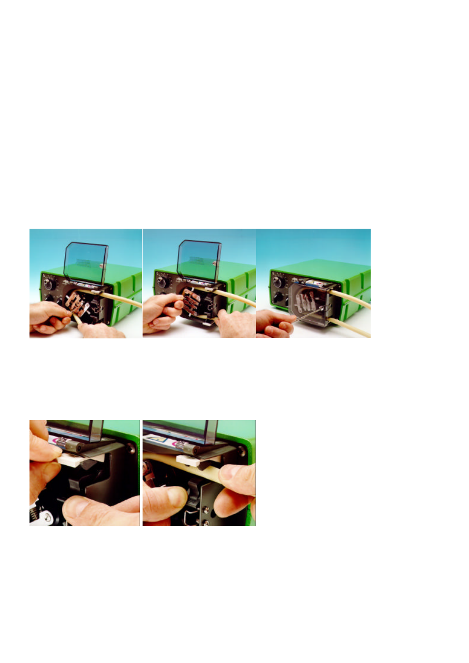
Tube loading
Isolate pump from mains supply. Unlock and open the hinged guard and swing out the rotor crank handle until it locks into
position. Select the length of tubing required, noting that approximately 240mm is required for the track systems.
Fit one end of the tubing into one of the spring loaded clamps, and then, whilst rotating the rotor with the crank handle, feed the
tubing between the rollers and the track, aligning it within the rotor tube guides. The tubing must lie naturally against the track
and must not be twisted or stretched.
Fit the other end of the tubing into the second spring loaded clamp, ensuring that the tubing is not slack in the pumphead, since
this can reduce tube life.
Close the crank handle and shut and lock the guard.
After the pump has been started, open the delivery clamp for a short time, so that the tube can find its natural length.
The 501RL pumphead is fitted with four-position tube clamps, to accommodate various tube diameters, which can be adjusted
by pushing in or pulling out the bars at the top of the upper clamp and the bottom of the lower clamp. Set the clamps so that the
minimum necessary pressure is applied to the tubing.
Roller adjustment
The 501RL has a factory set gap of 2.6mm between the rollers and the track and is suitable for tubing having wall thicknesses of
between 1.6 and 2.0mm. Adjustment of the gap will be required if tubing having a wall thickness of less than 1.6mm is required.
There is an adjusting screw on each of the two roller arms, and each of these screws will require adjustment. The correct gap is
twice the wall thickness less twenty percent. Correct adjustment is important: over occlusion will reduce tube life; under
occlusion will reduce pumping efficiency.
To change the gap setting, turn each adjusting screw clockwise to increase the gap, or anticlockwise to decrease the gap. A full
turn changes the gap by 0.8mm.To restore the original settings of 2.6mm, turn the adjusting screws until both rollers are just