Watson-Marlow 205S User Manual
Page 5
5
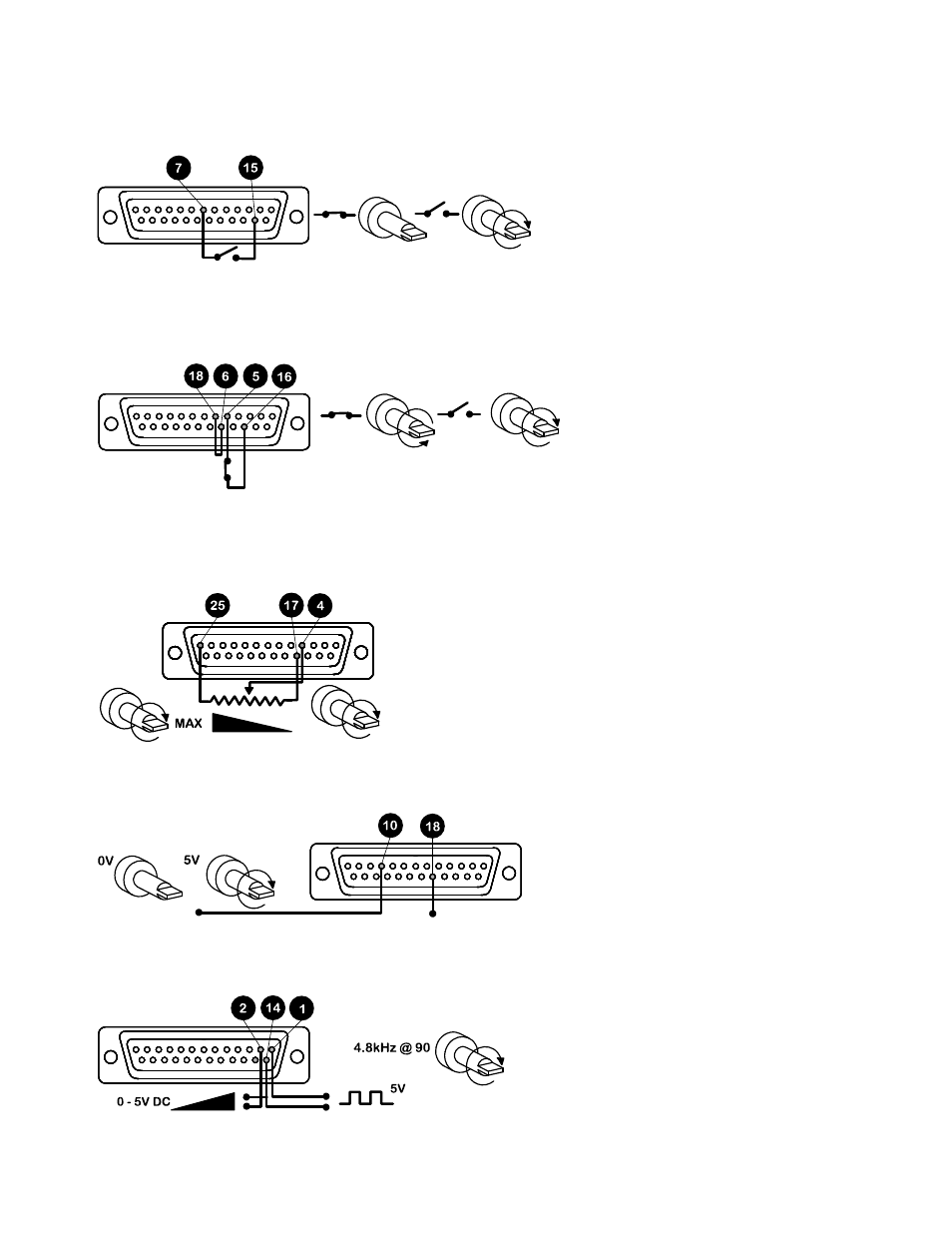
Remote control
Stop/Start
Connect remote switch between pins 7 and 15 of the 25D connector. A TTL compatible logic input (Low 0V, High 5V)
may be applied to pin 7. Low input stops the pump, high input runs the pump. With no connection, the pump will
default to running.
Direction
Connect remote switch between pins 5 and 16 and disable the front panel reversing control by linking pins 6 and 18 of
the 25D connector. Open switch for clockwise rotation, close for counter-clockwise. Alternatively a TTL compatible
logic input (Low 0, High 5V) may be applied to pin 5. Low input will run the pump in a counter-clockwise direction,
High input in a clockwise rotation. No connection; the pump will default to clockwise rotation.
Speed
A remote potentiometer with a nominal value of between 1k and 2k with a minimum of 0.25W should be wired as
shown. When using a remote potentiometer, do not apply a voltage/current control input signal at the same time. The
speed control signal will require calibration relative to the minimum and maximum settings of the potentiometer. Use
the offset and range potentiometers as described under calibration.
Strobe
The state of the pump may be monitored by utilising a 5V Hi Lo signal available at the 25D remote socket on the
pump rear panel. The strobe line will change state as soon as the motor starts or stops.
Tachometer output
This facility can be used to indicate motor speed or total the number of motor revolutions.
90rpm 4.8 kHz