Watson-Marlow 205S User Manual
Page 4
4
205U Automatic operation
Press the Man/Auto key. When the AUT symbol flashes the pump is in manual mode.
The pump is controllable by an analogue process signal of up to 30V or 32mA. The pump will provide an increasing
flow rate for rising control signal (non-inverted response ) or an increasing flow rate for falling control signal (inverted
response ).
Signal offset is the process signal level which has to be reached in order for the pump rotor to start rotating.
Signal range is the change in process signal level necessary to produce the required change in pump rotor speed.
For example, when using a 4mA to 20mA process signal:
Pump response
Signal offset
Signal range
Non-Inverted 4mA
16mA
Inverted 20mA
16mA
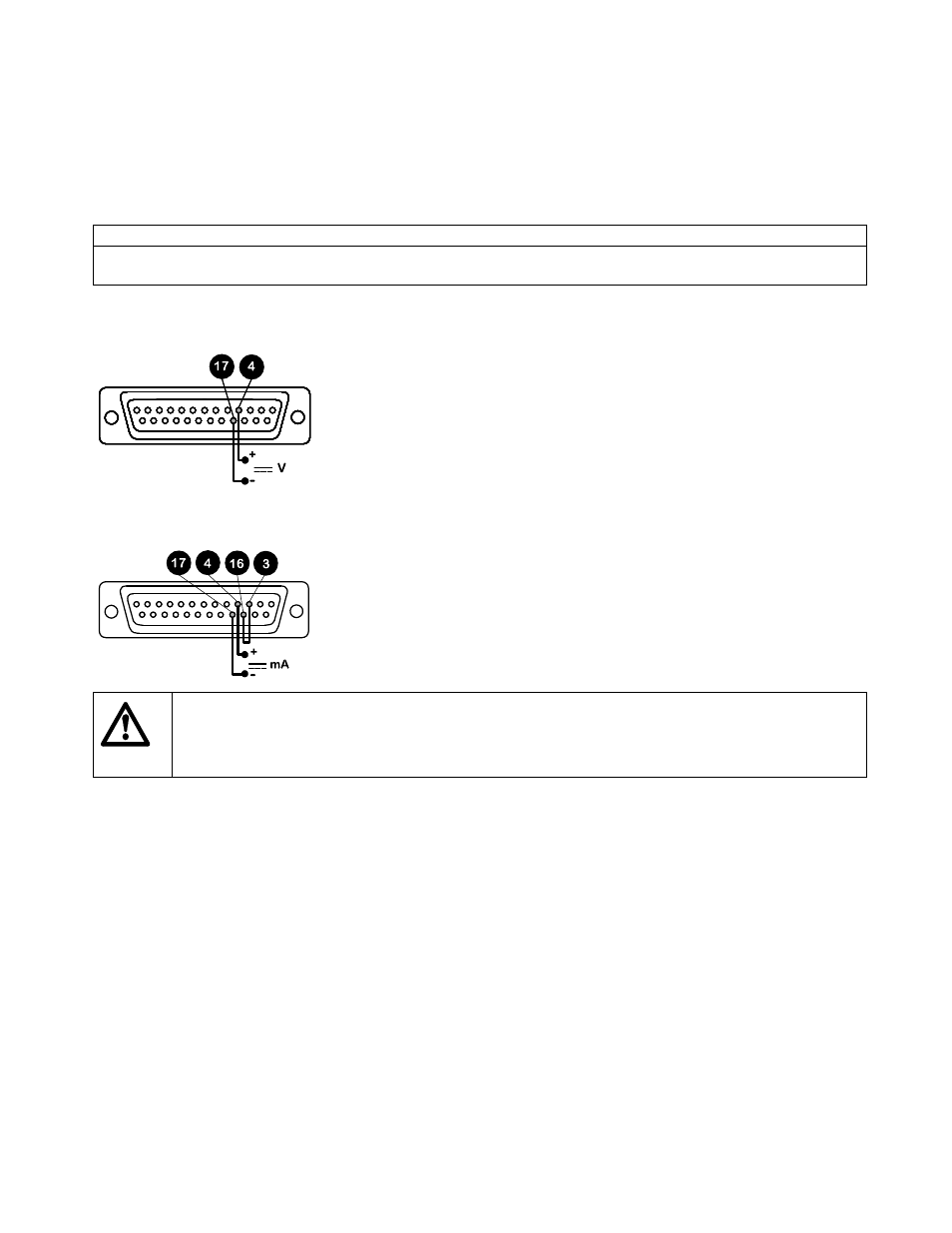
For voltage modes a stable variable DC voltage source can be used in conjunction with a DC voltmeter, (maximum
30V DC). (Refer to 25D pin connector wiring detail as an example of control circuitry) Circuit impedance 100 kohms.
Polarity set for non-inverted response. Reverse polarity for inverted response.
For current modes the same DC source can be used in conjunction with a DC milliampere meter, (maximum 32mA).
(See 25 pin Dee connector detail). Circuit impedance 250 ohms. Polarity set for non-inverted response. Reverse
polarity for inverted response.
Never apply mains voltage across any pins on the 25D socket. Up to 30V may be applied across
pins 4 and 17, and 5V TTL on pins 7 and 5, but no voltage should be applied across other pins.
Permanent damage, not covered by warranty may result in both instances. Do not use the mains
power switch to control the pump for a high repetition of stop/starts. The auto-control facility
should be used.
Calibration procedure
Turn the signal offset potentiometer (marked "Offset" on back panel) clockwise until the slider traverse limit is
reached and is signified by a clicking noise. Now turn the potentiometer ten turns anticlockwise. Repeat for the
signal range potentiometer. This ensures correct potentiometer set up for calibration.
Set the process signal offset.
Turn the signal offset potentiometer clockwise to set the drive shaft speed to the desired minimum.
Set the process signal at its upper range limit (not exceeding 30V or 32mA).
Turn the signal range potentiometer (marked "Range" on back panel) clockwise to set the drive shaft speed to the
desired maximum.
If the process signal or drive speed are set above their designated maximums the drive will be overloaded which is
signified by the flashing of AUT. This is an indication of the limiting control and speed levels of the drive. Reset to
operate within these levels.
Repeat the procedure until pump response coincides exactly with the process signal.