Watson-Marlow 501CC User Manual
Page 4
4
DO
use valves with a straight fluid path.
DO
use slow sweeping bends with minimum radius equal to four to five times the tubing diameter.
DO
keep the pumphead rollers and track clean.
The self-priming nature of peristaltic pumps means valves are not required. Any valves fitted must cause minimum restriction to flow
in the pumping circuit.
When using Marprene tubing, after the first 30 minutes of running, re-tension the tube in the pumphead by releasing the tube clamp
on the delivery side a little and pulling the tube tight. This is to counteract the normal stretching that occurs with Marprene which can
go unnoticed and result in poor tube life.
Tube selection The chemical compatibility list published in the Watson-Marlow catalogue is only a guide. If in doubt about the
compatibility of a tube material and the duty fluid, request a tube sample card for immersion trials.
Installation
Pump
• Site the pump on a flat, horizontal, vibration-proof surface allowing a free flow of air around it. Ensure there is 0.5m of straight
tubing before the pumphead inlet and after the pumphead outlets. Close coupled simplex pumps will require bolting down with four
M8 bolts through the gearbox foot mounting holes.
AC Motor
• Ensure that mains voltage/frequency are in accordance with motor nameplate information.
• Secure protective conductor connections.
• If the motor is running in the wrong direction, interchange any two phases.
• Close unused cable entrance holes and the terminal box itself in a dust and watertight manner.
• A current overload relay should be fitted to a contact breaker. Connect the motor in accordance with the wiring diagram which will
be found in the motor terminal box.
• When a thermal protection switch is fitted in the motor, the leads will be found in the motor terminal box. They should be connected
to stop the pump if the switch operates. The switch will open circuit at an over temperature condition. See below for the connection
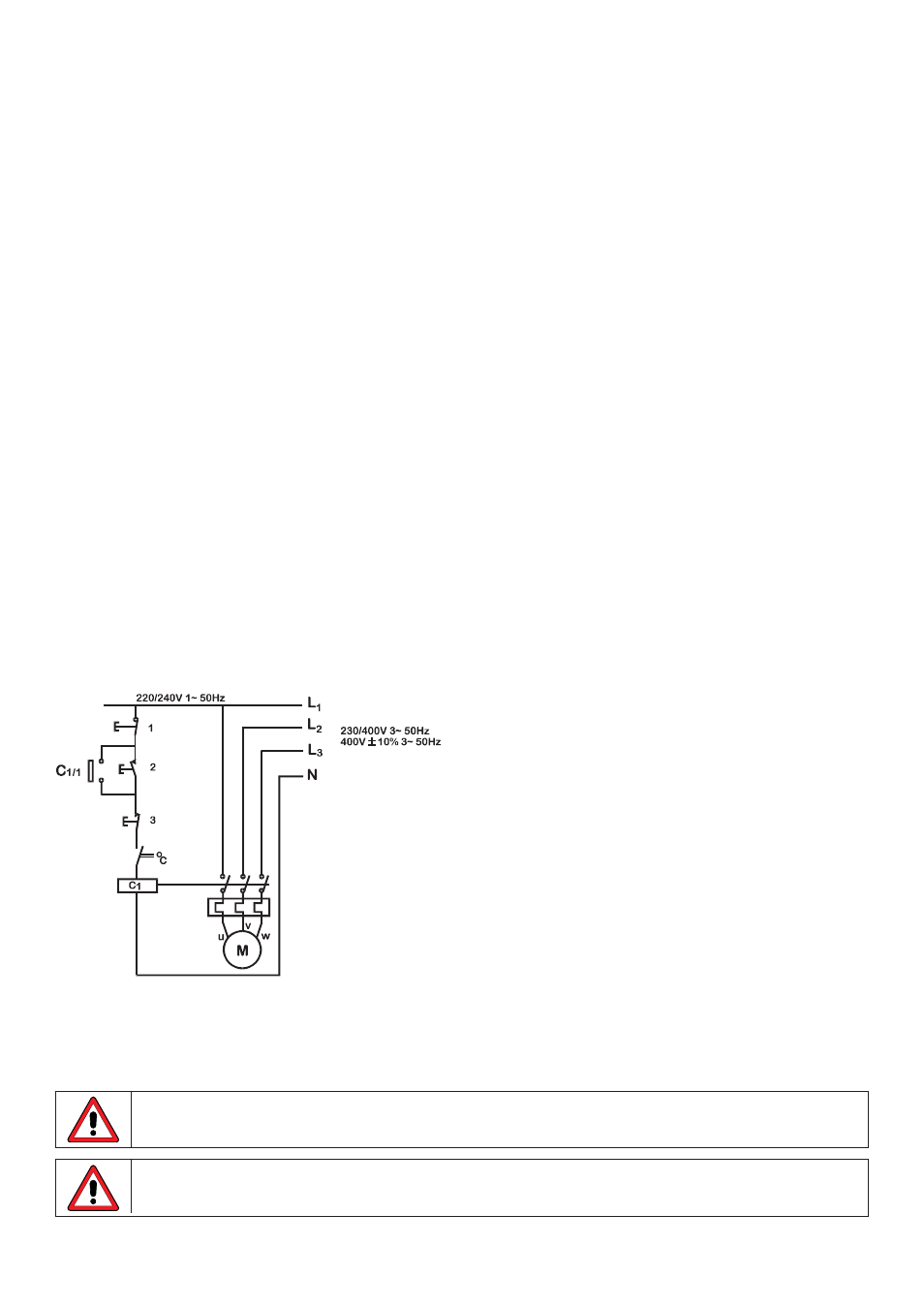
of the drive motor showing possible ancillary switches and protections.
1 Emergency stop 2 Start 3 Stop
The ancillary switches are rated to 220/240V 1ph 50Hz. The Start contact should have a sprung return which will disengage following
energisation of the coils C1 and C1/1.
Do not under any circumstances wire switches directly across any of the phases of a 3 phase supply. If in
doubt disconnect the pump immediately!
Do not connect ancillary switches to the terminal box of a flame proof motor unless the switch has a
suitable Exd rating for the zone area in which it is to be mounted.