Watson-Marlow 621CC User Manual
Page 8
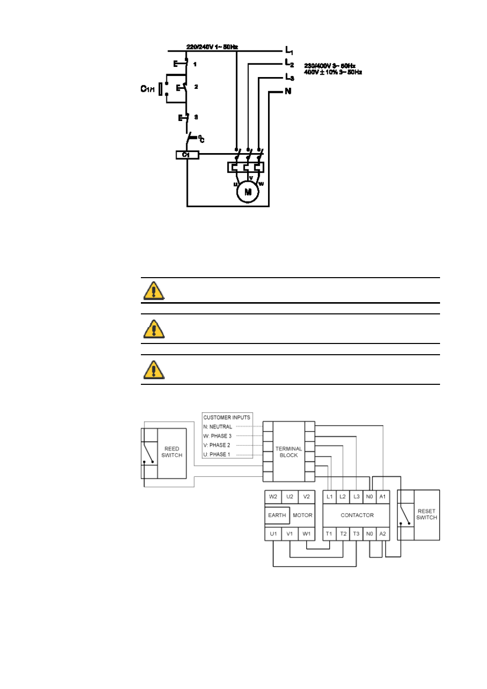
1. Emergency stop
2. Start
3. Stop
The ancillary switches are rated to 220/240V 1ph 50Hz. The Start contact should have a
sprung return which will disengage following energisation of the coils C1 and C1/1.
Wiring diagram for fixed speed motor fitted with guard switch option
Ensure that an emergency stop switch is fitted within reach of the pump.
Do not under any circumstances wire switches directly across any of the
phases of a three-phase supply. If in doubt disconnect the pump
immediately!
Do not connect ancillary switches to the terminal box of a flameproof
motor unless the switch has a suitable Exd rating for the zone area in
which it is to be mounted.
Page 8 of 46
Watson-Marlow Bredel E-Manuals
21/12/2011
file://R:\staging\pdfs-global\m-621cc-gb-04.html