5 varmeca drives: three-phase connection diagram, 6 varmeca drives: keypad indicator light display – Watson-Marlow 621CC User Manual
Page 13
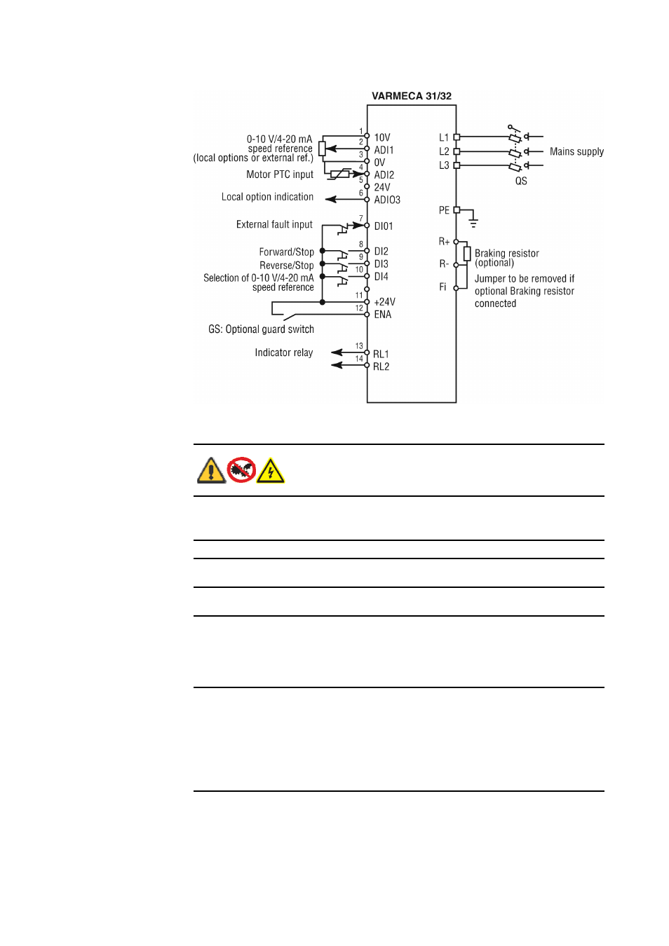
13.5 Varmeca drives: three-phase connection diagram
Note: For single-phase standards, the power supply is connected to terminals L and N.
13.6 Varmeca drives: keypad indicator light display
Before switching on the Varmeca-30 motor, check that
electrical connections are correct and that any moving parts
are mechanically protected. The Varmeca-30 must not be
switched on with the protective cover removed.
Indicator
Status
Checks to be performed
Steady green
light
No trip
Mains present
Flashing green
light
Current limiting
Check that the motor is not overloaded or stalled
Flashing red
light
IGBT temperature
alarm
Motor overload
Braking resistor option
overload
Check that air can circulate around the motor fins
and Varmeca casing
The motor is overloaded: check the motor
current using an ammeter
Check that the deceleration ramp is long enough
for applications with high inertia
Steady red
light
Short-circuit of a
motor winding
Locked motor rotor
Faulty insulation of a
winding
I²t overheating
Internal fault
Undervoltage
Overvoltage
Check that no incident has occurred
Switch off and on again to clear the fault
Check the mains voltage
Check that the deceleration ramp is long enough
for applications with high inertia
If the fault ramains, consult the manufacturer
Page 13 of 46
Watson-Marlow Bredel E-Manuals
21/12/2011
file://R:\staging\pdfs-global\m-621cc-gb-04.html