5 varmeca drives: single phase connection diagram, 6 varmeca drives: keypad indicator light display – Watson-Marlow 521CC User Manual
Page 14
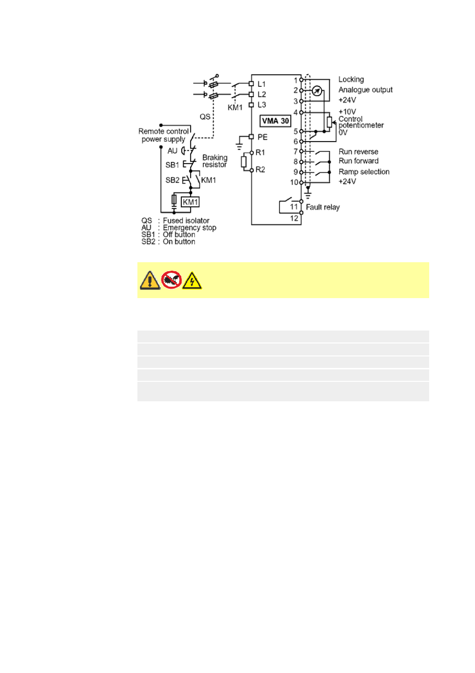
10.5 Varmeca drives: single phase connection diagram
10.6 Varmeca drives: keypad indicator light display
Before switching on the Varmeca-30 motor, check that
electrical connections are correct and that any moving parts
are mechanically protected. The Varmeca-30 must not be
switched on with the protective cover removed.
Steady green light
Mains connected
Flashing green light
Motor current overload
Flashing green and red lights
Motor current limit
Flashing red light
Fault: under/over voltage
Steady red light
Fault: short circuit; locked motor rotor; faulty winding
insulation; I²t overheating; or internal fault
Page 14 of 47
Watson-Marlow Bredel E-Manuals
14/12/2009
file://M:\staging\pdfs-global\m-521-cc-gb-03.htm
See also other documents in the category Watson-Marlow Pumps:
- 323Dz (53 pages)
- 620SN (100 pages)
- Bredel 25 (76 pages)
- APEX35 (72 pages)
- Bredel 80 (76 pages)
- Bredel 15 (68 pages)
- 520Bp (107 pages)
- 323D (48 pages)
- EBU250 (8 pages)
- FF20 (24 pages)
- MR-Series (52 pages)
- GD30P (14 pages)
- EC 60 (28 pages)
- PetroProof Series (49 pages)
- Qdos30 Universal (40 pages)
- Qdos60 Universal 110V Logic (78 pages)
- 120S/DM3 (36 pages)
- 120F/DV (26 pages)
- SP50 (86 pages)
- 101U (14 pages)
- 505BA (21 pages)
- 700 series (11 pages)
- Qdos60 Profibus (66 pages)
- 401U (12 pages)
- 620RE4A (11 pages)
- 405U (13 pages)
- 624S (46 pages)
- Bredel 2100 (96 pages)
- Bredel 2100 (92 pages)
- 701 (25 pages)
- 840 (13 pages)
- 505LGA (11 pages)
- 620RE4 (19 pages)
- 205U (13 pages)
- SPS (142 pages)
- 505U (19 pages)
- 704S (17 pages)
- 621 Trio (11 pages)
- 313T (16 pages)
- 624Di (37 pages)
- 505Di (39 pages)
- 501CC (17 pages)
- 504Du (30 pages)
- 504Du (30 pages)