Watson-Marlow 501RL User Manual
Page 18
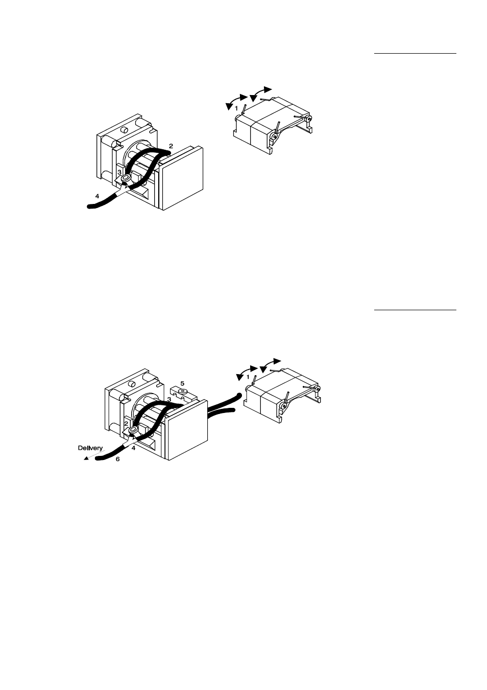
Lift the two levers (1) at either side of the pumphead and remove the track.
Stretching the tubing element slightly (2), locate it over the "pegs" at either
side of the pumphead (3).
Fitting Watson-
Marlow Double-
Y tubing
elements
Replace the track and pull down the securing levers.
Transfer tubing (4) may now be attached to the connectors and is available
from Watson-Marlow. It is advised to use 2.4mm wall tubing for transfer tubing
(to match the double tube elements) as this will give the best performance
under suction.
Lift the two levers (1) at each side of the pumphead and remove the track, as
above. Remove the "peg" on the inlet side. Do not remove the delivery side
peg (2).
Using twin inlet
tubes
Take the two lengths (3) of tubing to be used and insert the appropriate "Y"
connector (4). Lay this assembly across the rotor, with the "Y" connector over
the end peg on the delivery side (2). Whilst pulling the tubing taught from the
inlet side, take the correct tube clamp (5) (all tube clamps are marked with the
nominal bore for their intended tubing) and firmly secure using the same fixing
as the end peg. It is found to be easier to insert the two tubes into the
"arches" of the clamp before securing the clamp itself.
Replace the track and pull down the securing levers and connect the delivery
tube (6) to the output of the "Y" connector.
19