Part 5 : 505l pumphead description, Installation – Watson-Marlow 501RL User Manual
Page 15
Part 5 : 505L pumphead
Description
This design of peristaltic pumphead is Watson-Marlow's most accurate dosing
and dispensing pumphead. To overcome the pulsatile effect many peristaltic
pumps exhibit, Watson-Marlow have developed the principle of twin offset
tracks. This puts the two tubes out of phase, merging a pulse from one
channel with a trough from the other.
The 505L is fitted with six stainless steel rollers and uses either silicone or
Marprene tubing up to 9.6mm bore, to further increase accuracy, 2.4mm wall
thickness is used. With a 50% greater wall thickness than standard tubing,
505L tube elements are more stable under changing conditions of pressure,
suction and viscosity. The increase of bore size compared to standard 500
series pumpheads gives increased flow rates to over 2.4 litres per minute at
220rpm.
Silicone tubing will give the highest accuracy, but Marprene or Bioprene may
be a better choice where chemical compatibility is a problem, or extra long
tube life is required. For most dispensing and low pulse applications, we
would strongly advise the use of Watson-Marlow double-Y tubing elements,
which are pre-formed to the correct length to ensure accurate merging of
flows to give the smoothest flow possible. If you do not wish to use the special
double-tube elements you will need to order a set of six tube clamps which
will enable the pumphead to be used with either twin inlet (suction) tubes or
as a two channel (totally separate) precision pumphead.
One 505LX extension pumphead can be fitted to 503P, 504S, 504U, 505Di,
505S, 505U and 505Du drives to increase flow rates still further or to provide
another individual pumping channel.
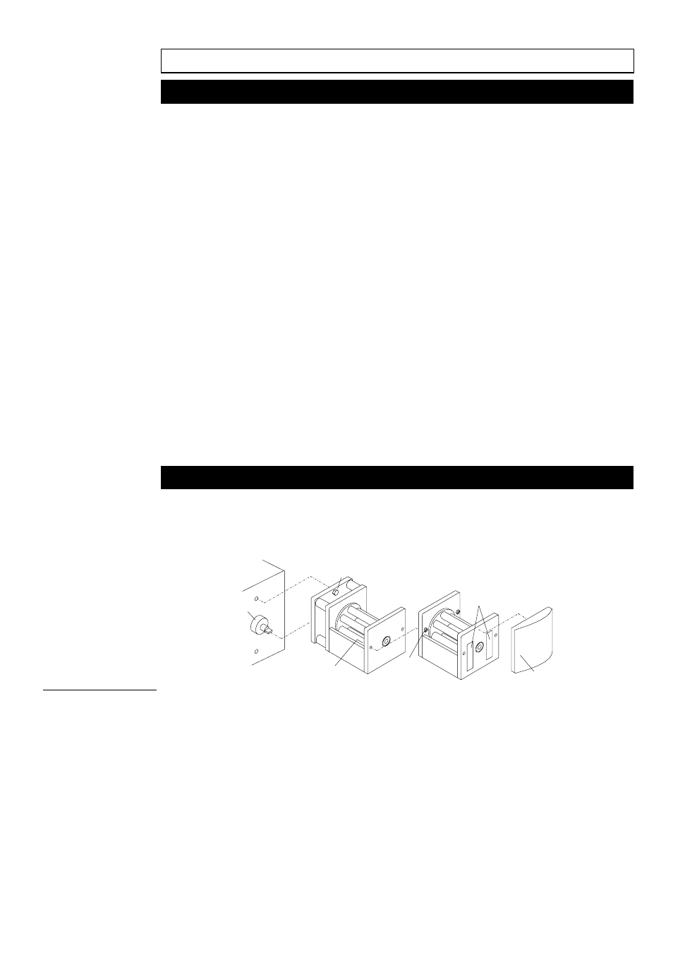
Installation
Remove the drive-shaft cover from the 205/505LA and fit the pumphead over
the drive "nose" (1), ensuring that the tongue on the drive shaft locates on the
slot in the pumphead centre shaft. Tighten the two retaining screws (2) at the
top and bottom of the mounting plate.
1
2
3
4
5
6
To remove the end cover plate (3) on the first pumphead, take one of the
extension pumphead fixing bolts supplied and screw into the tapped holes (4),
from the rear of the front plate, breaking the adhesion and pushing off the
cover plate. Grease the shaft tongue on the extension pumphead with the
grease supplied. Locate the tongue of the extension head drive shaft into the
slot in the centre shaft of the first pumphead and tighten the two extension
head fixing screws (5), at each side of the extension pumphead. The
extension head is supplied with two strips of industrial adhesive tape (6). Peel
off the cover strips and relocate the cover plate on the extension pumphead.
Fitting an
extension
pumphead
16