Verilink PRISM 3111 (CG) Configuration/Installation Guide User Manual
Configuration guide, Specifications
Specifications
Network Interface
Line Rate:
1.544 Mbps (
±
50 ppm)
Line Framing:
D4 or ESF
Line Code:
AMI or B8ZS
Input Signal:
0 to
−
27 dB ALBO
Connection:
RJ-48C jack, 100
Ω
(
±
5%)
Output Signal:
3.0 V (
±
10%) base –peak into
100
Ω
with protection
Line Build Out: 0,
−
7.5,
−
15,
−
22.5 dB
attenuation
Transient Voltage: 1000 V protection, fused
in/ out
Jitter Control:
per TR 62411 and T1.403
Timing Source:
Internal, recovered line clock,
external DTE, T1 DTE
Ones Density:
B8ZS, Nx56 bit stuffing,
alternate fill; TR 62411
Equipment Interface
DTE Ports:
3111 single and 3112 dual
Compatibility:
ITU V.35, female 34-pin
EIA-530, female 25-pin
Data Rate:
Synchronous, Nx56 kbps or
Nx64 kbps (where N = 1 to
24); independent selection on
each port
Clocking:
Internal, External,
Oversample
Data Invert:
Independent selection on
each port
Supervisory Port
Connection:
8- pin modular (RS-232)
Data Rates:
1.2, 2.4, 9.6, and 19.2 kbps
SLIP Port
Connection:
8- pin modular (RS-232)
Data Rates:
1.2, 2.4, 9.6, and 19.2 kbps
Ethernet (option)
Connection:
8- pin modular (RJ-45)
Network Protocol: TCP/IP-based networks
Data Rate:
10 Mbps
Compatibility:
10BASE- T
Token Ring (option)
Connection:
8- pin modular (RJ-45)
Network Protocol: TCP/IP-based networks
Data Rate:
4 or 16 Mbps
Compatibility:
Type 3 unshielded twisted
pair
T1 DTE (option)
Line Rate:
1.544 Mbps, ± 50 ppm
Line Framing:
D4 or ESF
Line Code:
AMI or B8ZS
Input Signal:
DSX1 to
−
6 dB
Connection:
RJ-48C modular jack
(100
Ω,
± 5%)
Output Signal:
Selectable DSX1 level from 0
to 655 feet in six increments
Dial Backup
Connection:
RS-232, 10-pin modular
Backup Service: PSTN external device
Configuration:
Information for backup unit
is stored in unit and
transmitted to backup unit by
in-band AT commands
Dialing:
Numbers programmed and
stored in unit and transmitted
to backup unit by in-band AT
commands or DTR dialing
(assertion)
Restoral:
Manual or automatic restoral
to leased line service
Diagnostics
Performance:
Monitoring per TR 54016
and T1.403
Network Loops: Line, payload, or
maintenance loopback
Fractional Loop: Generates and responds to
in-band V.54 loop
DTE Port Loops: Bidirectional loop toward
DTE and network
T1 DTE Loops: MLB and LLB toward DTE
BERT:
Multiple test patterns toward
network or DTE ports
Alarms
Activation:
Programmable thresholds
Reporting:
Front panel LEDs, call out on
alarm (COA), SNMP traps
Power
115 VAC:
120 mA, 7 W max,
24 BTU max
48 VDC:
180 mA, 9 W max,
31 BTU max
Mechanical
Mounting:
Desktop or horizontal rack
Dimensions:
11.75" (29.8 cm) wide
1.75" (4.45 cm) high
9.5" (24.1 cm) deep
Weight:
3 pounds (1.36 kg)
Environmental
Storage Temp:
32
°
to 122
°
F (0
°
to 50
°
C)
Operating Temp:
−
4
°
to 185
°
F (
−
20
°
to 85
°
C)
Humidity:
95% maximum
(non-condensing)
TEST
LOOP
BACKUP
NET
TEST ALARM POWER
PRISM 3111
T
R
A
N
S
P
O
R
T
®
SCROLL
EXIT
SELECT
BACKUP TEST ALARM POWER
PRISM 3111
T
R
A
N
S
P
O
R
T
®
45-00103
6.0
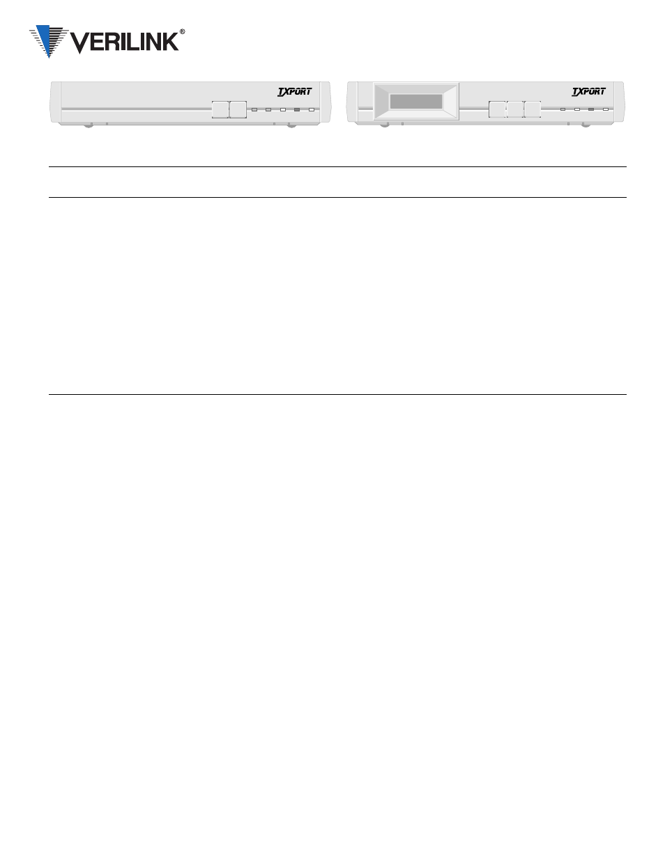
PRISM 3111/3112
Configuration Guide
PRISM 3111 with LCD Option
PRISM 3111
Button or
Indicator
Unit
Description
TEST
Non-LCD Press once to transmit five seconds of in-band loop code network. If S2-8 is set to Clear Loop, the unit goes into test mode and
does not generate an alarm. If S2-8 is set to BERT, the last test pattern selected in the terminal interface is transmitted toward
the network.
LOOP
Non-LCD Press once to activate a line loopback. Press again, to clear the loop and turn off the LOOP indicator.
EXIT
LCD
The EXIT button allows exiting a current menu option which then places the unit in the next higher menu level. If the unit is at
the main menu, pressing EXIT logs off the unit.
SCROLL LCD
The SCROLL button allows reviewing the options or selections for a menu level.
SELECT LCD
The SELECT button allows choosing the option or value for a field.
NET
Non-LCD This indicator is green when the unit is in frame sync; amber when receiving a yellow alarm from the far end; and red when out
of sync and/or has lost signal.
BACKUP Both
This amber indicator flashes when dialling, connecting, or disconnecting. This indicator is on continuously when active.
TEST
Both
This indicator flashes green when the unit transmits loop code. It is green continuously when a BERT has no errors, the unit has
a loop, or when the unit is in clear test. It is red during a BERT when the unit receives errors.
ALARM
Both
This red indicator is on continuously when the unit has an active alarm. It flashes when an invalid switch setting has been made.
POWER
Both
This green indicator is on when power is applied to the unit.