Prism 3021, Switch s1, Switch s2 – Verilink PRISM 3021 (CG) Configuration/Installation Guide User Manual
Page 2: Switch s3, Switch sw1, Switch s4, E1-dte option switch s1
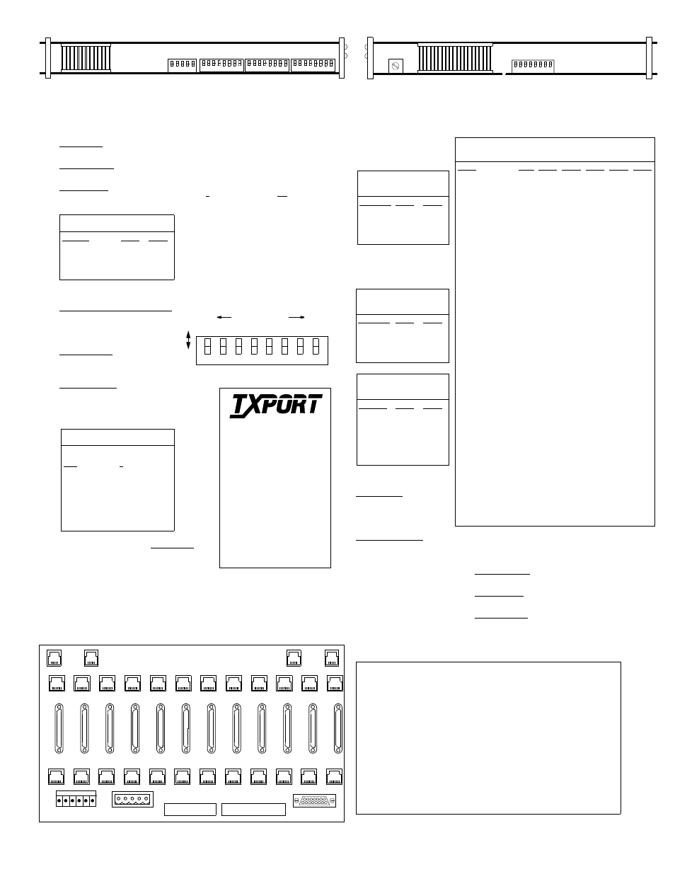
T
OP
-E
DGE
V
IEW
OF
THE
PRISM 3021
Factory default settings are underlined.
Rear Panel Connections
Pin
E1 NET
(labeled
T1 NET)
NMS IN
NMS
OUT
TB1
Network/
Clock
TB2
Alarm/
Power
E1 DTE
(labeled T1
DTE)
1
Data In
Not Used
Not Used
Ntwk In
48-V Return
Tip Output
2
Data In
Signal Gnd Signal Gnd Ntwk In
Signal Gnd
Ring Output
3
Not Used
Data Out
Data Out
Ntwk Out
-48 VDC
Not Used
4
Data Out
Data In
Not Used
Ntwk Out
Frame Gnd
Tip Input
5
Data Out
Signal Gnd Signal Gnd Station Clk Alm Contact
Ring Input
6
Not Used
Not Used
Not Used
Station Clk Common
Not Used
7
Not Used
N/A
N/A
N/A
N/A
Chassis Gnd
8
Not Used
N/A
N/A
N/A
N/A
Chassis Gnd
*
B
OTTOM
-E
DGE
V
IEW
OF
THE
PRISM 3021
Switch S1
8
1 2 3 4 5 6 7
E1-DTE Option Switch S1
1
8
7
6
5
4
3
2
Switch SW1
0
12
34
5
678
9
Switch S1
S1-1:Sets network framing.
Down: CAS
Up: CCS
S1-2:Sets CRC4.
Down: Enabled Up: Disabled
S1-3:Selects network line code.
Down: HDB3
Up: AMI
S1-4 and S1-5: Select the unit’s timing
source.
S1-6:Selects keep alive framed and
unframed ones.
Down: Keep alive unframed ones
Up: Keep alive framed ones
S1-7:Selects normal or inverted data
mode.
Down: Normal Up: Inverted
S1-8:Used for programming the Flash
memory.
Down: Disabled Up: Enabled
Timing Source
S1-4
S1-5
Network
Down
Down
Internal
Down
Up
E1 DTE
Up
Down
DTE or External
Up
Up
Switch S2
Switch S2 sets the unit address. When using the
3021 with an 8100A Site Controller, each ele-
ment in a group must have a unique unit
address. As many as 50 units (with addresses
from 1 to 50) can exist in a group. If the unit is
not connected to a site controller, the NMS unit
address should be left at the factory default set-
ting of 1 where Position 1 is Up and all other
positions are Down.
Switch S2 has eight positions used to create an
8- bit binary code for an address in the range of
1 to 50. Switch position S2 -1 is the least signif-
icant bit (LSB) and S2-8 is the most significant
bit (MSB). If a switch is down, its value is 0. If
up, its value is that of the upper location. The
values are additive. For example, to set a unit
address to 5, position S2-3 (binary value is 4)
and position S2-1 (binary value is 1) would be
set Up for a unit address of 5 (4 + 1). All other
positions would be set Down.
7
6
5
4
3
2
1
8
LSB
MSB
binary values
Do
w
n
Up
1
2
4
8 16 32 64 128
0
0
0
0
0
0
0
0
Switch S2
8
1 2 3 4 5 6 7
Switch S3
8
1 2 3 4 5 6 7
Switch S4
1 2 3 4 5
Switch S3
S3-1 and S3-2:Set the NMS
port rate. Configure the port
for 8 bits, no parity, and 1
stop bit.
S3-3 and S3-4:Set the SUPV
port rate. Configure the port
for 8 bits, no parity, and 1
stop bit.
S3-5 and S3-6:Set the boot mode.
S3-7:Selects the DTE rate
multiplier.
Down: N
×
64
Up: N
×
56
S3-8:Selects the channel
assignment mode.
Down: Contiguous
Up: Alternating
NMS
Port Rate
S3-1
S3-2
19200 bps Down
Down
9600 bps
Down
Up
2400 bps
Up
Down
1200 bps
Up
Up
SUPV
Port Rate
S3-3
S3-4
38400 bps Down
Down
19200 bps Down
Up
9600 bps
Up
Down
2400 bps
Up
Up
Boot
Mode
S3-5
S3-6
Switches
Down
Down
RAM
Down
Up
ROM
Up
Down
Reserved
for future
expansion.
Up
Up
Switch SW1
SW1:Sets the national bit.
National Bit
Switch Position
None
0
SA4
1
SA5
2
SA6
3
SA7
4
SA8
5
None
6-9
Switch S4
S4-1 through S4-5:Set the DTE rate.
DTE
Rate
N
×
56
(kbps)
N
×
64
(kbps)
S4-1
S4-2
S4-3
S4-4
S4-5
N= 31
1,2
1736
1984 Down Down Down Down Down
N= 30
1
1680
1920 Up
Down Down Down Down
N= 29
1
1624
1856 Down Up
Down Down Down
N= 28
1
1568
1792 Up
Up
Down Down Down
N= 27
1
1512
1728 Down Down Up
Down Down
N= 26
1
1456
1664 Up
Down Up
Down Down
N= 25
1
1400
1600 Down Up
Up
Down Down
N= 24
1
1344
1536 Up
Up
Up
Down Down
N= 23
1
1288
1472 Down Down Down Up
Down
N= 22
1
1232
1408 Up
Down Down Up
Down
N= 21
1
1176
1344 Down Up
Down Up
Down
N= 20
1
1120
1280 Up
Up
Down Up
Down
N= 19
1
1064
1216 Down Down Up
Up
Down
N= 18
1
1008
1152 Up
Down Up
Up
Down
N= 17
1
952
1088 Down Up
Up
Up
Down
N= 16
1
896
1024 Up
Up
Up
Up
Down
N= 15
840
960 Down Down Down Down Up
N= 14
784
896 Up
Down Down Down Up
N= 13
728
832 Down Up
Down Down Up
N= 12
672
768 Up
Up
Down Down Up
N= 11
616
704 Down Down Up
Down Up
N= 10
560
640 Up
Down Up
Down Up
N= 9
504
576 Down Up
Up
Down Up
N= 8
448
512 Up
Up
Up
Down Up
N= 7
392
448 Down Down Down Up
Up
N= 6
336
384 Up
Down Down Up
Up
N= 5
280
320 Down Up
Down Up
Up
N= 4
224
256 Up
Up
Down Up
Up
N= 3
168
192 Down Down Up
Up
Up
N= 2
112
128 Up
Down Up
Up
Up
N= 1
56
64 Down Up
Up
Up
Up
1
This selection is not valid if the Channel Assignment is set to Alternating.
2
This selection is not valid for CAS mode.
127 Jetplex Circle
Madison, Alabama 35748
Sales and Marketing
800 - 926- 0085
205 - 772- 3770
Returns and RMA
800 - 926 - 0085, ext. 2227
Technical Support
800 - 258- 2755
205 -772 -3770
T
R
A
N
S
P
O
R
T
®
E1-DTE Option Switch S1
S1-1:Sets CRC4.
Down: Enabled Up: Disabled
S1-2:Selects the E1-DTE line code.
Down: HBD3
Up: AMI
S1-8:Selects the E1-DTE line termination.
Down: 75 ohm Up: 120 ohm
T1 DTE
( B )
NMS
IN
( B )
NMS
OUT
HIGH SPEED DTE
T1 NET
TB1
TB2
ENET
( A )
NMS
IN
( A )
NMS
OUT
TB1
TB2
Rear Panel of the TxPORT 1051-2 Chassis
1
2
3
4
5
6
7
8
9
10
11
12
1
2
3
4
5
6
7
8
9
10
11
12
12
8
7
6
5
4
3
2
10
11
1
9
For 3021 applications, read E1 in place of T1 on the rear of the 1051 chassis.