Verilink PRISM 3021 (CG) Configuration/Installation Guide User Manual
Configuration guide, Front panel description, Specifications
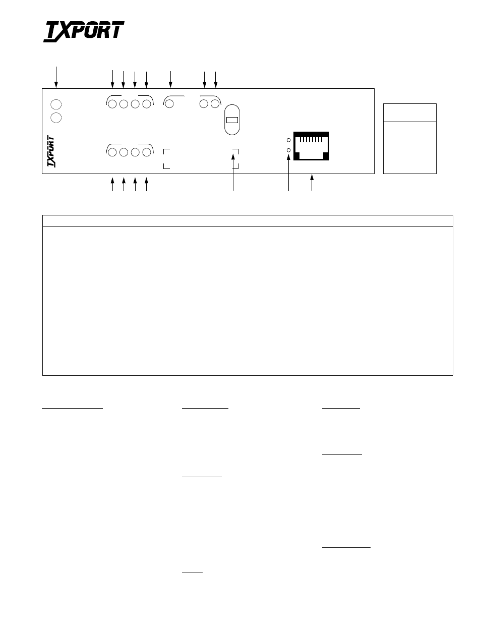
Front Panel Description
Index
Item
Function
1
STATUS
If neither LED is On, the 3021 is not powered. If only the green LED is On, the 3021 is powered and may be functioning normally. If only the red LED is On, there
is a fault that exceeds alarm thresholds or another type of 3021 failure.
2
TD
This green LED is On during a mark condition on the high-speed transmit data line.
3
RD
This green LED is On during a mark condition on the high-speed receive data line.
4
RTS
This green LED is On when the request-to-send signal is active.
5
DTR
This green LED is On when the data-terminal-ready signal is active.
6
FAR/LOC
Switch
This switch is used for local testing and setting the SUPV port rate when downloading firmware for the Flash PROM. For testing, setting the switch to LOC performs a network
LLB and setting the switch to FAR sends five seconds of in-band loop code and then sends the BERT pattern selected in the user interface. The default pattern is QRSS.
7
Activity
Indicators
These two small, recessed LEDs indicate supervisory/network manager port activity.
8
SUPV Port
The supervisory jack provides direct terminal access to control and monitor the 3021.
9
BV/CR/FE
This LED is On when the unit detects bipolar violations, cyclic redundancy checking errors, or framing errors.
10
LOS/OOF
This LED flashes when the unit detects a loss-of-signal condition or remains On during an out-of-frame condition.
11
AIS
This LED is On when the network interface is receiving an alarm indication signal.
12
REM ALM
This LED is On when the network interface is receiving a remote alarm indication.
13
LOOP
This LED is On when the network interface is in a line loopback.
14
TST
This LED is On when a BERT is in progress.
15
ERR
This LED is On when BERT pattern errors are detected.
T
R
A
N
S
P
O
R
T
®
3021 E1 NTU/DSU
Configuration Guide
45-00112
1.0
Specifications
Network Interface
Service Types:
CEPT/E1
Line Rate:
2.048 Mbps (
±
50 ppm)
Framing:
CAS or CCS
Line Code:
AMI or HDB3
Input Signal:
0 to -22.5 dB ALBO
Line Connection:
75
Ω
:
BNC
120
Ω
: DB-15
,
twinax,
and RJ- 48
Output Signal:
Per G.703 with 75-
Ω
or
120-
Ω
option
Surge Protection:
1000 volts
High-Speed Data
Port Compatibility: ITU V.35 female
DB-25, female 34-pin
through adapter cable,
ITU X.21 female
DB-15; EIA-530 DB-25
Rate:
Synchronous, N
×
56, or
N
×
64 kbps (N = 1 to 31)
Clocking:
Internal or external
Data Invert:
Enabled or disabled
Configuration
Configuration:
Card-edge switches
Terminal interface on the
supervisory port, Telnet
session using the 8100A
SNMP Management
System. Soft configura-
tion is non-volatile.
Diagnostics
Performance:
RFC1406 (with the 8100A)
Status:
Front panel LEDs for
network, testing, and DTE
Network Loopbacks: Line, payload,
and proprietary
E1-DTE Loopbacks: Line and proprietary
DTE Loopbacks:
Responds to V.54 in-band
loop codes and performs
bidirectional fractional-
port loopback
Power
Power:
- 48 VDC, 150 mA, max;
7.2 W, (24.6 BTU, max)
Mechanical
Mounting:
Wall, vertical, horizontal
rack, TxPORT 1051
chassis, or standalone
Weight:
1 pound, nominal
Compliance
FCC Compliance:
Part 15, Class A, Subpart B
US Safety:
UL 1950, 3rd Ed. (Pending)
Canadian Safety:
CSA: C22.2 No. 950- 95
(Pending)
G.703:
Signal Waveform
G.704:
Framing
G.732:
Multiframing
G.823:
Jitter
G.831:
Framing Requirement
Environmental
Operating Temp:
0
°
to 50
°
C (32
°
to 122
°
F)
Storage Temp:
-20
°
to 85
°
C (-4
°
to 185
°
F)
Relative Humidity:
95% max., non-condensing
LO
C
FA
R
D T E
TD
RD
RT
S
DT
R
ST
A
T
US
TRANSPORT
®
E1 CSU/DS
U
N E T
BV/CR/
F
E
L
O
S
/OOF
AIS
REM
AL
M
LO
O
P
TS
T
ERR
2
3
4
11
12
5
6
7
8
9
10
1
13
14
15
S
U
P
V
1
8
3021
T S T
SUPV Port
Pin
SUPV Port
Interface
1
Control Out
2
Signal Ground
3
Data Out
4
Data In
5
Signal Ground
6
Control In