Prism 3000, Network bert testing – Verilink PRISM 3000 (CG) Configuration/Installation Guide User Manual
Page 2
ALARM TEST POWER
SELECT
CLR
EXIT
1
TxPORT PRISM 3000
S/N:xxx
HW Rev x.xx
SW Rev x.xx
PRISM 3000
2
3
4
5
6
7
8
9
T
R
A
N
S
P
O
R
T
®
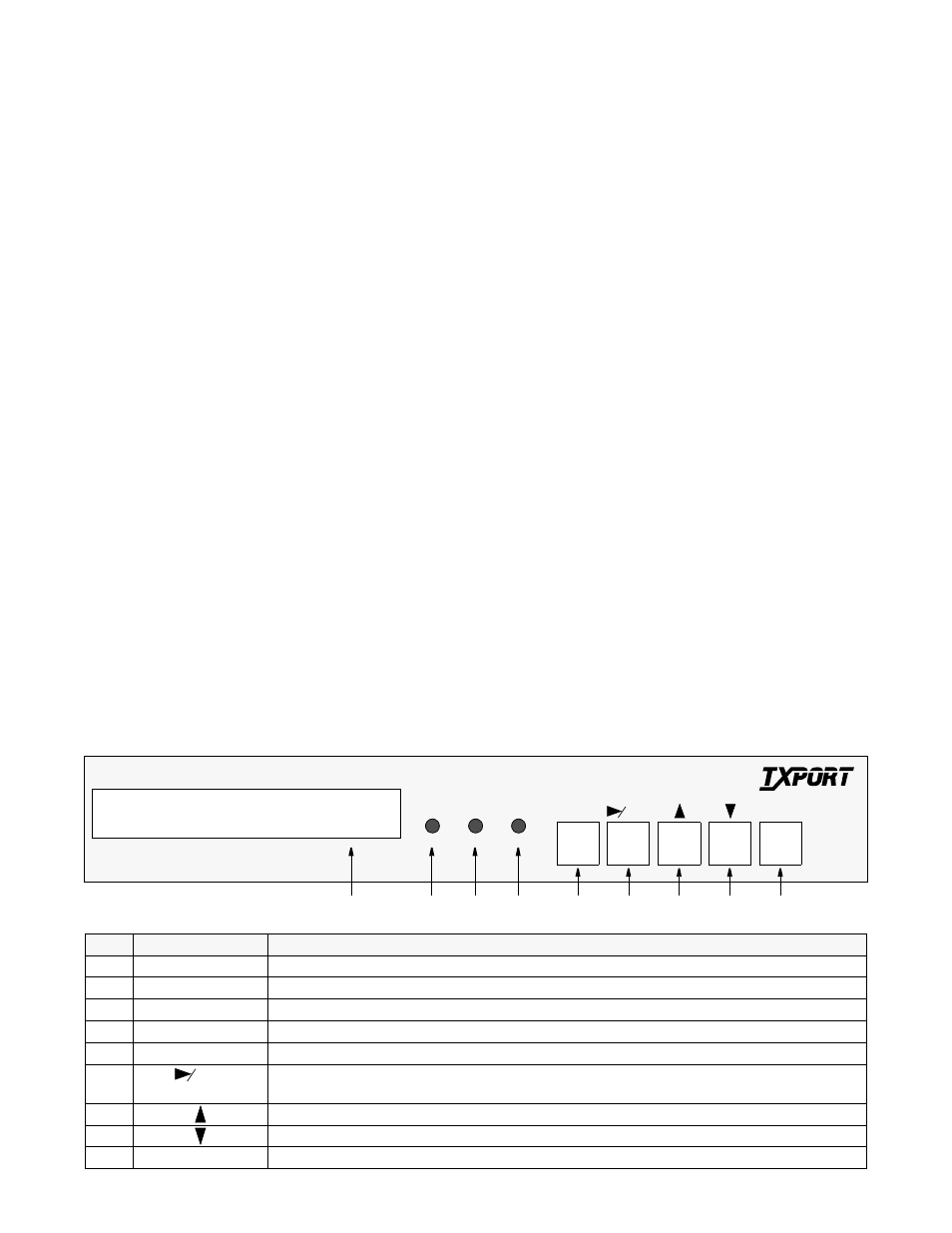
Index
Control/Indicator
Function
1
LCD Display
This 2- line, 40- character window provides access to unit configuration, diagnostics, and utilities.
2
ALARM (red)
This LED lights continuously when the unit is in an active alarm condition.
3
TEST (yellow)
This LED lights continuously when line or DTE loops are set or if the BERT function is operating.
4
POWER (green)
This LED lights continuously when power is applied to the unit.
5
EXIT
Pressing this button returns the user to the previous menu.
6
CLR
Pressing the ‘Clear’ button moves the cursor one character to the right or clears the error counts. Pressing
this button on power up resets all parameters to the factory defaults.
7
Pressing this button allows the user to scroll up through the elements/parameters.
8
Pressing this button allows the user to scroll down through the elements/parameters.
9
SELECT
Pressing this button accesses a submenu or sets a parameter to the displayed value.
Network BERT Testing
The following front panel test procedures are recommended
in order to activate the BERT generator and perform end-to-
end or local testing.
1)
From the ‘Main Menu’, select ‘
T1
NET
Configura-
tion
’, then select the ‘
Timing
’ source. ‘
Network
’ is the
most common selection. This allows the unit to derive tim-
ing from the T1 line.
2)
From the ‘Main Menu’, select ‘
Diagnostics
’, then
‘
BERT
Function
’, then ‘
BERT
Port
’. The choices are:
Network
- Tests all channels mapped to the network.
T1
DTE
- Tests all channels associated with the T1 DTE
port.
Port
1, 2, 3, or 4 - Selecting any of these ports tests all
channels associated with that port.
The amber ‘Test’ indicator should now be on.
3)
Select the ‘
BERT
Channel
’ option. This menu item is
available only when ‘
BERT
Port
’ is set to ‘
Network
’.
This allows selection of a specific DS0 channel (1 to 24) to
be tested. Only unassigned (idle) channels will appear as
selections. If ‘
ALL
’ is selected, the entire T1 bandwidth will
be tested. If ‘
IDLE
’ is selected, all unassigned channels are
tested. Excluded are ports which are assigned as ‘
Alter-
nate
’ channels.
4)
Select ‘
BERT
Pattern
’ to specify which pattern will
be transmitted toward the port being tested. ‘
3
in
24
’ is
recommended for all end-to-end stress testing (for AMI/
B8ZS signals, ‘
1
in
8
’ is recommended).
5)
Select ‘
BERT
Direction
’. The choices are ‘
Toward
Network
’ and ‘
Toward DTE
’. If the ‘
BERT
Port
’ menu
is set to ‘
Network
’, the BERT direction is automatically
forced toward the network and this option does not appear.
6)
Select ‘
BERT
Results
’. If the local unit has a modu-
lar loopback plug installed or if the remote unit is config-
ured identically to the local unit, ‘
Sync
Status
’ should
indicate ‘
IN
SYNC
’. When running a local BERT test, the
timing source must be set to ‘
Internal
’, provided no
other timing source is used. When running end-to-end tests
using a far and local unit, only one timing source can be
used. The following are display only fields showing test
results.
Sync
Status
: This field displays the current state of
pattern sync during a test. ‘
NO SYNC
’ indicates that no test
is in progress.
Elapsed
Time
: This field displays the elapsed time
since a timed test began. A value is displayed only when a
test is running.
Bit
Errors
: This field displays the total number of bit
errors detected since the test began or since error statistics
were last cleared.
Errored
Seconds
: This field displays the number of
errored seconds that have been detected since the test began
or since error statistics were last cleared.
Pattern
Sync
Loss
: This field displays the number of
times during the test period that the BERT pattern detector
lost sync.
Reset
BERT
Test
: If this option is selected, both BERT
error counts and elapsed time values are cleared to zero.