Verilink 310 (CG) (CG) Configuration/Installation Guide User Manual
310 csu/dsu, Productivity series 310, Configuration guide
SD
RD
FRAME
ERROR
YELLOW
TEST
NORM
RL
LL
CSU/DSU
PRODUCTIVITY
SERIES
310
SPECIFICATIONS
Network Interface
Line Rate:
1.544 Mbps (± 50 bps)
Line Framing:
D4 or ESF
Line Code:
AMI or B8ZS
Line Impedance: balanced 100
Ω
(± 5%)
Input Signal:
DS1, +1 to - 27 dB (ALBO)
Output Signal:
3.0 V (± 15%) base-peak into
100
Ω
Line Build Out:
0, -7.5, -15, and -22.5 dB atten-
uation
Line Protection: 1000 V lightning, input/output
Jitter Control:
per TR62411 and T1.403
Pulse Density:
per TR62411
V.35 Interface
Data Rate:
Synch, N x 56 or N x 64 kbps
Clocking:
Internal or external
Industry Standards
FCC:
Part 15 Subpart B, Class A
UL
1459 2
nd
Edition
CSA:
C22.2 No. 225M-90
IC:
CSO3 Issue 8
TR 62411:
December 1990
TR54019: April
1988
Mechanical
Mounting:
Desktop, wall, or vertical rack
Dimensions:
1.75 inches (4.45 cm) high
6.8 inches (17.27 cm) wide
10.5 inches (26.67 cm) deep
2 pounds (0.91 kg)
Power
AC Power:
115 VAC (± 10%), 150 mA max,
20 Watts, 73 BTU max.
Connection: 5-foot
power
cord
Environmental
Operating Temp: 32° to 122°F (0° to 50° C)
Storage Temp:
- 4° to 185°F (-20° to 85° C)
Humidity:
95% max (non - condensing)
1
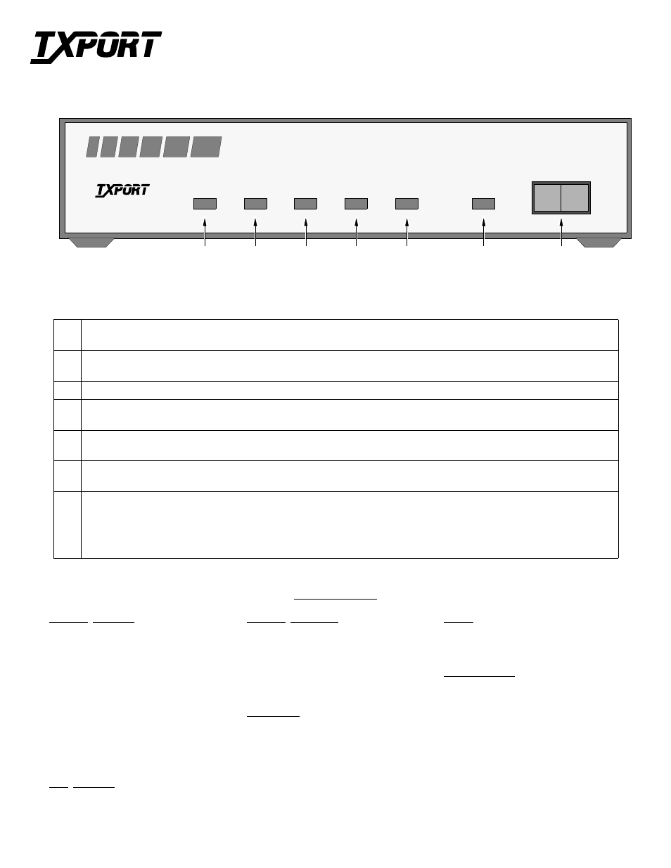
Send Data: This green LED lights when the SD data lead is a mark and is off when the lead is a space.
Therefore, the LED will vary from full intensity to off depending on the relative number of marks and spaces.
2
Receive Data: This green LED lights when the RD data lead is a mark and is off when the lead is a space.
Therefore, the LED will vary from full intensity to off depending on the relative number of marks and spaces.
3
Frame: This green LED lights when the unit is in frame synchronization with the T1 line.
4
Error: This red LED lights if the internal alarm circuitry detects any of the following conditions from the incoming T1 signal:
BPVs, FBEs, CRCs, loss of signal/loss of sync, or more than 175 zeros.
5
Yellow: This red LED lights if the internal alarm circuitry detects a remote (yellow) alarm signal from the far end terminal equipment.
This occurs if the far end terminal is out of sync with the T1 signal from the network.
6
Test: This amber LED remains lit if the unit is in a test mode, either by manually depressing the loop switch or by receipt of a test
command from the facility.
7
Test Switch: This 3-position switch is used as follows: Depressing the switch to the ‘LL’ position places the unit in a local loop
mode. Data from the DTE is looped back to the DTE and is also transmitted to the network (the data from the network is open).
Depressing the switch to the ‘RL’ position initiates an automated V.54 remote loop and BERT sequence of assigned data channels. The
‘TEST’ LED will be green if the test is successful (the far end unit loops and returns the data error free with the V.54 code). If errors
are detected, the ‘TEST’ LED will be red.
T
R
A
N
S
P
O
R
T
®
310 CSU/DSU
Configuration Guide
Part Number 45-00045
Rev 2.0
7
6
5
4
3
2
1
Front Panel Description
T
R
A
N
S
P
O
R
T
®