Connector pinout, Rear panel, Rear panel description – Verilink 1061 Multicast Card (CG) Configuration/Installation Guide User Manual
Page 2: T1 multicast port pinout
Connector Pinout
Pin
NMS Out
NMS In
EXPAND
T1 IN
Alarm/Power
1
Not Used
Not Used
Data Out
Data In
External Alarm A (+)
2
Signal Gnd
Signal Gnd
Data Out
Data In
External Alarm A (-)
3
Data Out
Data Out
Not Used
Not Used
External Alarm B (+)
4
Not Used
Data In
Data In
Data Out
External Alarm B (-)
5
Signal Gnd
Signal Gnd
Data In
Data Out
48 VDC Return
6
Not Used
Not Used
Not Used
Not Used
Alarm Common
7
Chassis Gnd
Chassis Gnd
-48 VDC
8
Chassis Gnd
Chassis Gnd
Frame Ground
9
Normally Closed
10
Normally Open
T
R
A
N
S
P
O
R
T
®
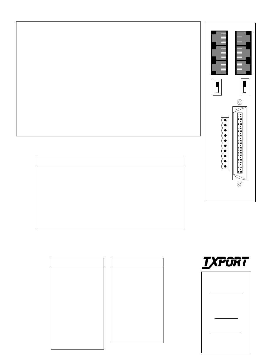
Rear Panel
8
1
8
1
10
1
1
81
8
UNTERM
48 VDC
Rear Panel Description
NMS (IN/OUT): These two ports connect the chassis to the TxPORT EM8000. Within the chassis, each unit
is physically connected to the next unit in a daisy chain. Each unit in the NMS chain must have a unique
address, however, they all use the same NMS bit rate.
Expand (A/B): These two 8-pin modular jacks expand the A or B inputs to other 1061 units providing
additional outputs. The maximum number of units is ten.
T1 IN (A/B): These two 8- pin modular jacks are used for the T1 input signal as well as the output of each
input. They output AIS with no input.
Terminate/Unterminate: These two slide switches set the A or B input. Terminate is used when the
expansion connector is not used. Unterminate is used when the expansion connector is daisy chained. The
recessed switches can be moved with a screwdriver. The last unit in a daisy chain must be terminated.
T1 Broadcast Port: This 50-pin female connector is used for the expanded outputs of either the A or B
inputs. Refer to the T1 Multicast Port Pinout table.
Alarm/Power: This 10-pin connector is used as a power and alarm connection. The unit requires a -48
VDC power source capable of supplying 100 mA current. The chassis ground lead is connected to pin 8. The
- 48 VDC lead is connected to pin 7. The return lead is connected to pin 5. The alarm connection is made on
pins 6 and 9 to operate in a normally closed mode (NC - opens on alarm) or on pins 6 and 10 to operate in a
normally open mode (NO - closes on alarm). The contacts are rated at 1.0 Amp AC or 1.0 Amp DC. 18 to 20
gauge wire is recommended. The external alarm connectors are unpowered, isolated inputs indicating
external alarms on inputs A and B. External alarm A is connected on pin 1 (+) and pin 2 (-). External alarm B
is connected on pin 3 (+) and pin 4 (-). They are 10 mA current loops and must be powered externally.
A
Tip Ring Function
1
26
Output # 1
2
27
Input # 1
3
28
Output # 2
4
29
Input # 2
5
30
Output # 3
6
31
Input # 3
7
32
Output # 4
8
33
Input # 4
9
34
Output # 5
10
35
Input # 5
11
36
Output # 6
12
37
Input # 6
13
38
Output # 7
26
50
25
1
14
39
Input # 7
15
40
Output # 8
16
41
Input # 8
17
42
Output # 9
18
43
Input # 9
19
44
Output # 10
20
45
Input # 10
21
46
Output # 11
22
47
Input # 11
23
48
Output # 12
24
49
Input # 12
25
50
Frame Gnd
Tip Ring Function
T1 Multicast Port Pinout
127 Jetplex Circle
Madison, Alabama 35758
Sales and Marteking
205-772-3770
800-926-0085
Returns/RMA
800-926-0085, ext. 2227
Technical Support
(205) 772-3770
800-285-2755
8
1
1
8
N
M
S
O
U
T
B
TERM
ALARM/
POWER
A
E
X
P
D
T1
A
-
I
N
N
M
S
I
N
B
E
X
P
D
T1
B
-
I
N
- - -
____