Verilink 1061 Multicast Card (CG) Configuration/Installation Guide User Manual
Configuration guide, Front panel description, Specifications
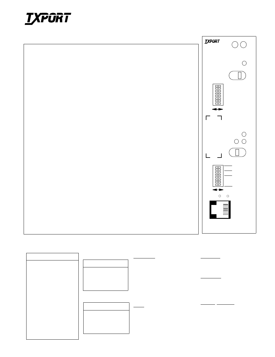
Front Panel Description
STATUS: Green LED illuminates when the unit is powered. Red LED illuminates when an alarm
exceeding thresholds is detected or other unit failure.
ACO: Amber LED illuminates when the Alarm Cutoff switch is On (switch left) indicating that the
alarm relay contacts are forced to the No Alarms condition.
ACO SW: Alarm Cutoff switch controls the alarm relay circuitry. When the switch is On (left), the
circuitry is deactivated. The ACO indicator still functions normally.
ADDRESS: This 8-position switch (Switch 1) sets the address of the unit targeted by the command from
the EM8000 controller. Valid addresses are 0 through 253 with zero being the broadcast address and 253
reserved as a universal hailing frequency.
FORCE: Amber LED illuminates when the select switch is in either the A or B position. NMS
commands will not override this switch.
A / B: Green LEDs illuminate indicating which input (A or B) is being broadcast to the ports. If both
ports (A and B) have input, only the selected port’s indicator illuminates.
Select: The select switch forces the input to either the A (switch left) or B (switch right) input. N (switch
center) is for normal operation.
NMS BR: S2-1 and S2-2 set the NMS bit rate. Refer to the NMS Bit Rate table below for setting
information.
SUPV BR: S2-3 and S2-4 set the Supervisory port bit rate. Refer to the SUPV Bit Rate table below for
setting information.
LSB: S2-5 sets the Least Significant Bit with respect to the duplex select. Refer to the Duplex Select
table for setting information.
Duplex Select: S2-6 and S2-7 select the channel (1-12) that is full duplexed to the selected (A or B) input
channel. No channel is selected when set to zero. The expansion settings (A EXPD, B EXPD, and A/B
EXPD) full duplex back to their respective T1 input lines. For example, the A EXPD setting full duplexes
the return feed back to the T1 A input line; the B EXPD setting full duplexes the return feed back to the
T1 B input line; and the A/B EXPD setting full duplexes the return feed back to the respective T1 A and
T1 B input lines.
MSB: S2-8 sets the Most Significant Bit with respect to the duplex select. Refer to the Duplex Select
table for setting information.
Activity Indicators: The two red activity indicators allow you to identify transmission flow in the unit.
The left light indicates supervisory port transmission. The right light indicates NMS bus transmission.
SUPV: The supervisory port allow you to configure the unit’s software through a VT100 connection.
T
R
A
N
S
P
O
R
T
®
T
R
A
N
S
P
O
R
T
®
Specifications
Input/Output
Input (A/ B):
Impedance terminated
100
Ω
(± 2 %)
Unterminated 1000
Ω
Ext. Alarm Inputs: Off when
≤
3 mA,
On when
>
4 mA and
≤
20 mA
Output: Per
62411
waveform
into 100
Ω
Power
DC Power:
-48 VDC (±10%), 100
mA max.
2.5 Watts, 8.5 BTU
max.
Connection:
Terminal block
Mechanical
Mounting:
Desktop, wall, horizon-
tal rack, vertical rack
or vertical nest mount
Dimensions
Width:
1.72 in (4.37 cm)
Height:
6.8 in (17.27 cm)
Depth:
10.5 in (50.90 cm)
Weight:
4.0 lbs (1.81 kg)
Industry Standards
FCC Compliance: Part 15 Class A,
Subpart B
U.S. Safety:
UL 1950 Third Edition
Canadian Safety:
CSA C22.2
No. 950-95
1061 T1 Multicast
Configuration Guide
45-00117
1.00
NMS Bit Rate
NMS BR
S2-1
S2-2
19.2 kbps
B
B
9.6 kbps
A
A
2.4 kbps
B
A
1.2 kbps
A
B
SUPV Bit Rate
Bit Rate
S2-3
S2-4
19.2 kbps
B
B
9.6 kbps
A
A
2.4 kbps
B
A
1.2 kbps
A
B
Duplex Select
S2-5 S2-6 S2-7 S2-8
0
B
B
B
B
1
A
B
B
B
2
B
A
B
B
3
A
A
B
B
4
B
B
A
B
5
A
B
A
B
6
B
A
A
B
7
A
A
A
B
8
B
B
B
A
9
A
B
B
A
10
B
A
B
A
11
A
A
B
A
12
B
B
A
A
A Expd
A
B
A
A
B Expd
B
A
A
A
A/B Expd
A
A
A
A
1061
Multicast
ADDRESS
FORCE
ACO SW
ACO
STATUS
A
B
N
A
B
B
A
NMS BR
S
U
P
V
SUPV BR
LSB
DUPLEX SEL
MSB