Configuration – Verilink DDS Lite (34-00295.C) Product Manual User Manual
Page 14
8
C
HAPTER
2: I
NSTALLATION
AND
C
ONFIGURATION
Configuration
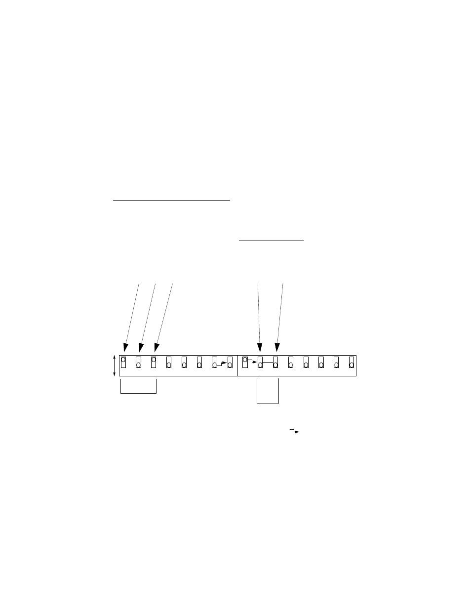
This section describes the configuration of the Multi-Rate DDS
CSU/DSU. This unit is configured using DIP switches shown in
Figure 2-1.
On power up, the unit configures to the hardware settings of
option switches SW1 and SW2. Changes to these settings take
effect after resetting the unit by removing and then reapplying
power. The unit then cycles through its LEDs and reads the new
configuration.
2
5
4
3
1
3
1
4
2
B
A
Rate
(kbps)
SW
1-1
SW
1- 2
SW
1-3
RTS - to -CTS
Delay (ms)
2.4 B
B
B
8.0
4.8 A
B
B
4.0
9.6 B
A
B
2.0
19.2 A
A
B
1.0
28.0
B
B
A
0.8
38.4
A
B
A
0.5
56.0 B
A
A
0.4
64.0
A
A
A
0.3
8
6
7
V
.54 D
isa
bl
ed
V
.54 Loop
En
abl
e
d
Da
ta
No
rm
a
l
Da
ta
I
n
v
e
rt
e
d
Channel
Bit Rate
Async
Word
Length
Ci
rc
u
it
As
su
ra
n
c
e
On
Ci
rc
ui
t A
ssu
ra
nce
O
ff
CTS For
ced
On
CT
S Nor
m
a
l
RT
S
-t
o
-C
T
S
D
e
la
y
×2
R
T
S
-t
o
-C
TS De
la
y
No
rm
a
l
Sync
hr
onou
s D
at
a
A
sy
n
ch
ron
ous
D
a
ta
*
Bits SW2- 2 SW2- 3
8
A
B
9
B
B
10
A
A
11
B
A
* Asynchronous data
does not function at
28, 56, and 64 kbps.
5
8
6
7
not
u
sed
no
t u
sed
no
t u
sed
no
t u
sed
no
t u
sed
not
u
sed
not
u
sed
not
u
sed
The symbol
indicates that the
switch pointed to does not function
unless the opposite end of the arrow
is in the position shown. For
example, SW1-8 functions only
when SW1-7 is in the A position.
Figure 2-1 Multi-Rate DDS CSU/DSU Configuration
Ba
si
c R
a
nge
(
−
2.
5 t
o
1
.0%
)
Ext
e
n
d
ed
Rang
e
(
−
2.
5 t
o
2.
3
%
)