Heat pump, Sample wiring diagrams, Page 10 – Venstar T1010 Installation User Manual
Page 11
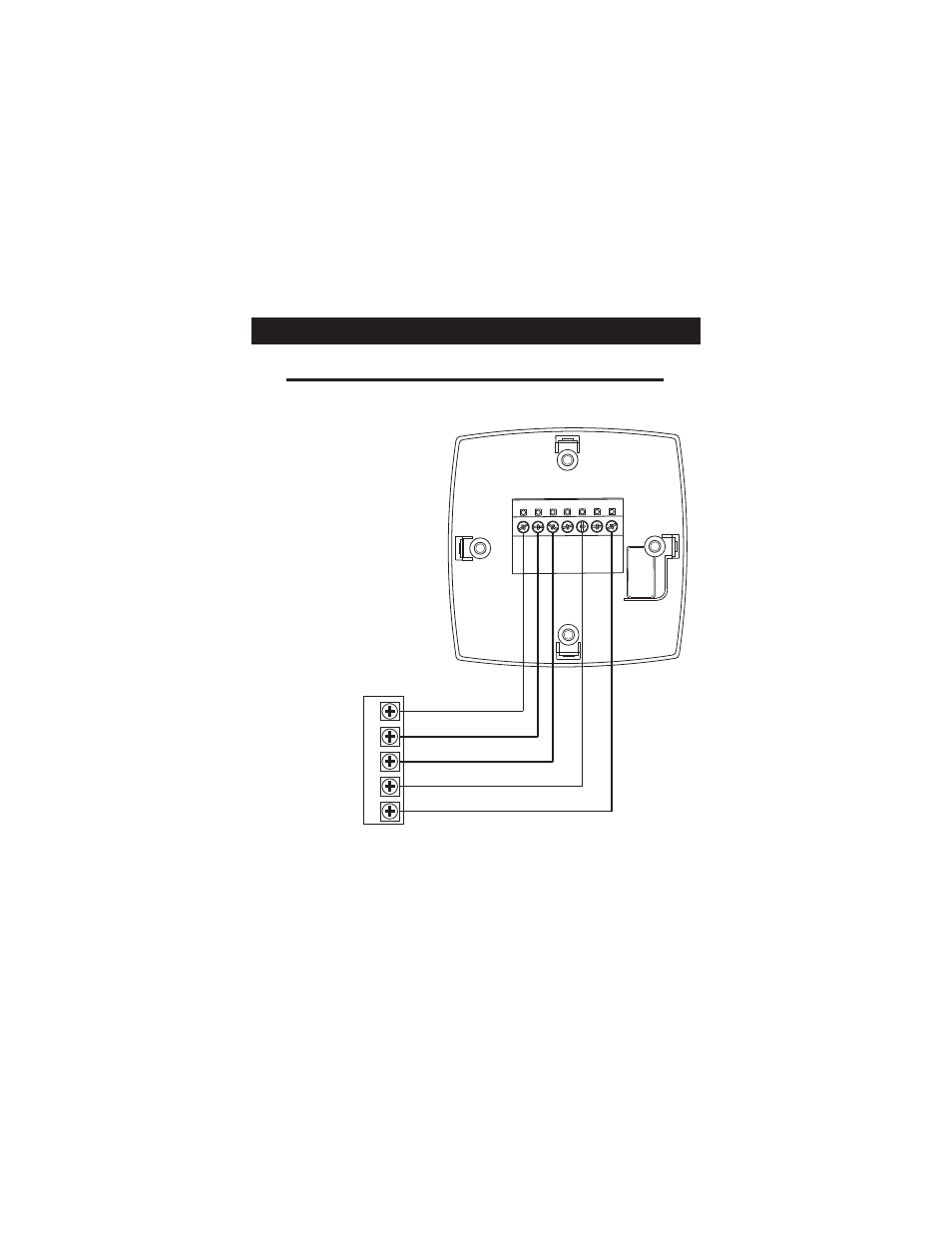
Sample Wiring Diagrams
* This option must be selected ON during advanced setup
(see page 11, step #4 of Owner’s Manual).
** This option must be selected O or b during advanced setup
(see page 11, step #5 of Owner’s Manual).
Heat Pump
5 Wire, 1 Stage Cooling, 1 Stage Heat-Heat Pump* with O or b reversing valve**.
Residential Heat Pumps, split systems & package units, with no auxiliary heat.
POWER
R
COMPRESSOR
Y
O
/B
REVERSING VALVE**
COMMON
C
FAN
G
C
G
R
Y1 W2 W1
O
B
Y2
Page 10
This manual is related to the following products: