Installation, General instruction, Ventilation – Dometic NDR1292-S User Manual
Page 4: Gas connection, Electrical connection
INSTALLATION
GENERAL INSTRUCTION
This appliance is designed for storage of foods and
storage of frozen foods and making ice.
The refrigerators outlined herein have been design cer-
tified
ANSI 221.19 Refrigerator Stan-
dard for installation in a mobile home or recreational
vehicle and are approved by the Canadian Gas Asso-
ciation.
The certifications are. however contingent on the instal-
lation being made in accordance with the following in-
structions as applicable.
In the U.S.A., the installation must conform with:
1. National Fuel Gas Code ANSI Z223.1.(latest
edition)
2. Manufactured Home Construction and Safety
Standard Title 24 CFR, Part 3280.
3. Recreational Vehicles ANSI Al 19.2.(latest edition).
The unit must be electrically grounded in accordance
with the National Electric Code
edition) when installed, if an external alternating current
electrical source is utilized.
4. Any applicable local code.
In CANADA, the installation must conform with:
1. Current CAN/CGA 8149 Gas Installation Codes
2. Current CSA Standard 2240.4 GAS-EQUIPPED
RECREATIONAL VEHICLES AND MOBILE
H O U S I N G .
3. Where a flexible metal connector is used, it must
comply with the provisions of the current Standard
METAL CONNECTORS FOR GAS
APPLIANCES.
4. Any applicable local code
The unit must be electrically grounded in accordance
with the current CANADIAN ELECTRICAL CODE C22
Parts 1 and 2.
VENTILATION
The installation shall be made in such a manner as to
separate the combustion system from the living space
of the mobile home or recreational vehicle. Openings
o f c o m b u s t i o n p r o d u c t s s h a l l
have a minimum dimension of not less than
inch.
Proper installation requires one lower fresh air intake
and one upper exhaust vent. The ventilation kits shown
in this instruction manual have been certified for use
with the refrigerator models listed in the table. For “Cer-
tified Vent System Kits” see page 14. The ventilation
kits must be installed and used without modification. An
opening toward the outside at floor level in the refrigera-
tor compartment must be provided for ventilation of
heavier-than-air fuel gases. The lower vent of the rec-
o m m e n d e d k i t s i s p r o v i d e d w i t h p r o p e r s i z e o p e n i n g s .
The flow of combustion and ventilating air must not be
obstructed.
4
The lower side vent is fitted with a panel, which pro-
vides an adequate access opening for ready service-
ability of the burner and control manifold of the refrig-
erator. This should be centered on the back of the re-
frigerator.
GAS CONNECTION
Hook-up to the gas supply line is accomplished at the
manual gas valve, which is furnished with a
SAE
(UNF
male flare connection. All completed con-
nections should be checked for leaks with soapy water.
DO NOT use a flame to check for gas leaks.
The gas supply system must incorporate a pressure
regulator to maintain a supply pressure of not more than
11 inches water column.
When testing the gas supply system at test pressures in
excess of
psig. the refrigerator and its individual
shutoff valve must be disconnected from the gas supply
system.
When testing the gas supply system at pressures less
than or equal to
psig, the appliance must be isolated
from the gas supply piping system by closing its indi-
vidual manual shutoff valve.
In case detailed instructions on the installation and con-
nection to the gas supply are required, contact your
dealer or distributor.
ELECTRICAL CONNECTION
120
AC Connection
The refrigerator is equipped with a three-prong (ground-
ing) plug for your protection against shock hazards and
should be plugged directly into a properly grounded
three-prong receptacle. DO NOT cut or remove the
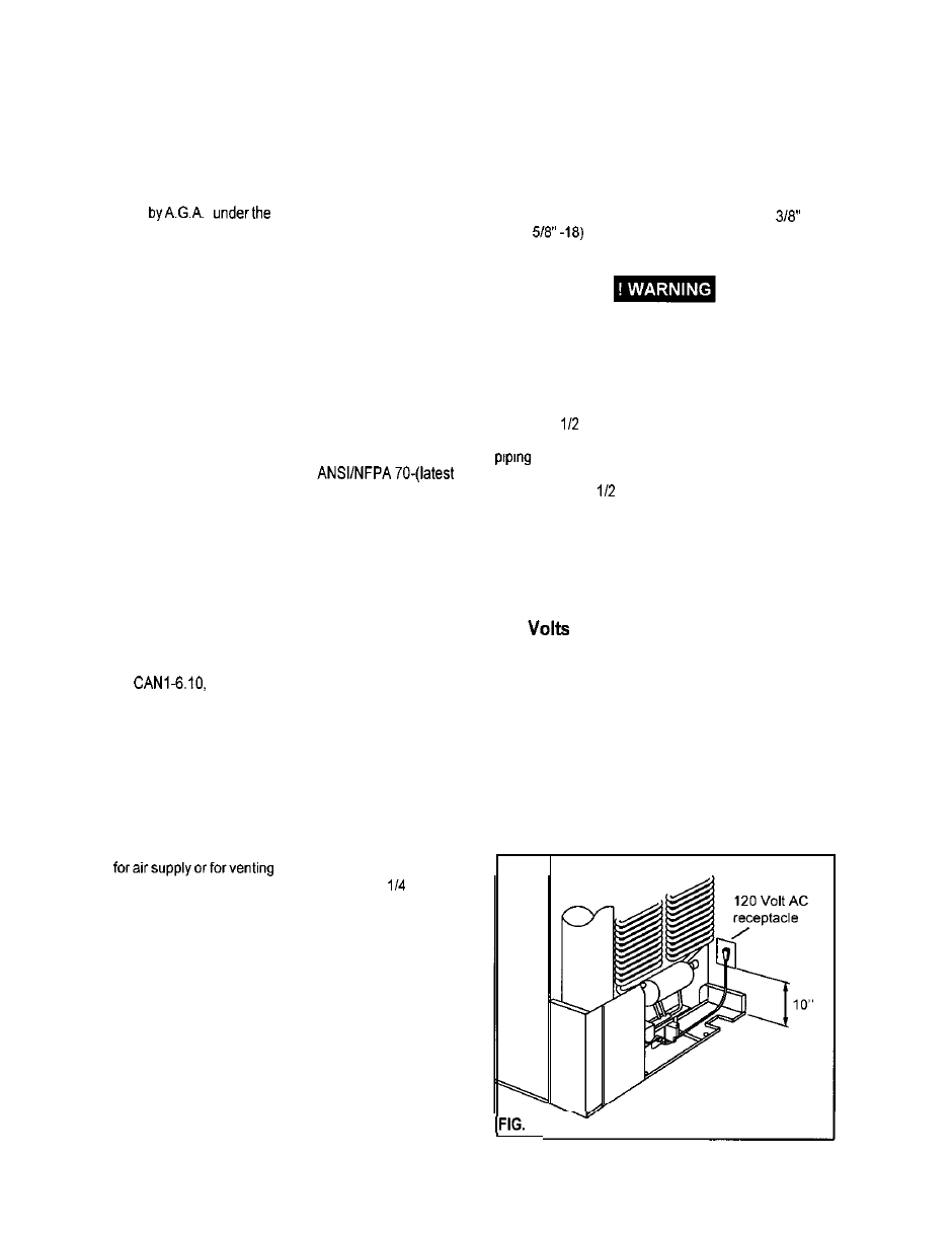
grounding prong from this plug. The free length of the
cord is 2 feet and therefore recommended that the re-
ceptacle be located to the right side of the refrigerator
(viewed from the rear) and approximately 10 inches from
the floor (see FIG. 3). This allows easy access through
the vent door. The cord should be routed to avoid direct
contact with the burner cover. flue cover or any other
components that could damage the cord insulation,
3