Installation, Continued – Desa VMH10TPC User Manual
Page 15
www.desatech.com
112462-01F
15
3
2
1
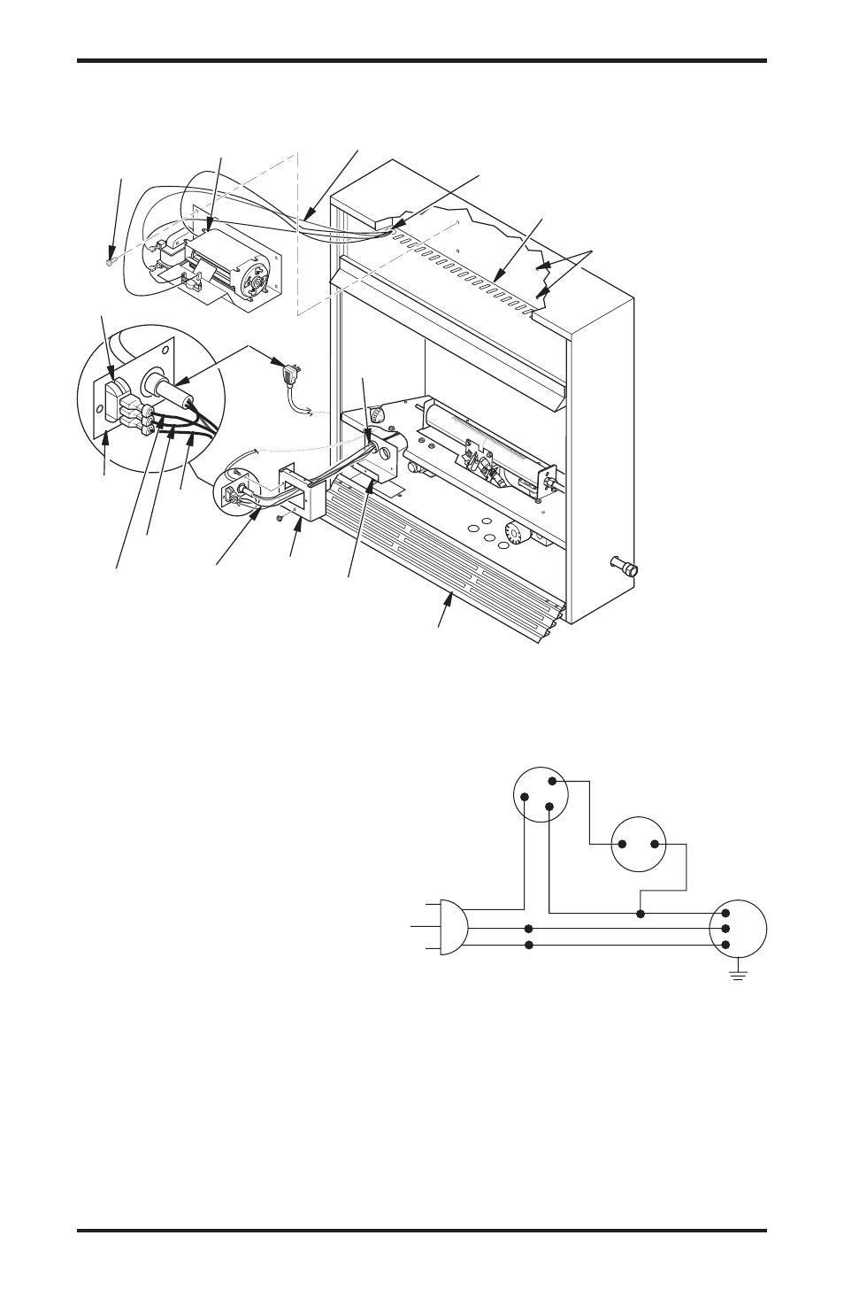
Figure 16 - Installing Blower (Thermostat Unit Shown)
Wire Harness
Blower Bracket Assembly
Screw
Wire
Harness
Switch
Baffle
Wiring Routing Hole
in Baffle
Switch
Plate
Blue
Red
Rear Fan
Switch Cover
Snap
Bushing
Power Cord
Black
Blower Mounting
Holes
Lower Louver Door
Front Fan
Switch
Cover
INSTALLATION
Continued
6. In top of the fireplace cabinet, locate the
four mounting holes on the outer casing.
Align these four holes with those on the
blower bracket assembly. Attach blower
bracket assembly to the outer casing with
4 #10 screws provided (see Figure 16).
7. Route the wire harness through the hole
in left side of baffle. Pull wire harness
through lower opening of firebox (see
Figure 16).
8. Insert the 4 wire harnesses into one of the
round holes in the rear of the fan switch cover
and through the rectangular hole on front of
the fan switch cover (see Figure 16).
9. Reconnect red wire to switch position 3.
Reconnect blue wire to switch position 1.
Reconnect green and white wires.
10. Install the switch plate on front of fan
switch cover with 2 #10 screws provided
(see Figure 18, page 16). Using screw
removed in step one, reconnect front and
rear of fan switch cover.
Figure 17 - Wiring Diagram For Blower
Accessory Standard Installation
Red
Red
Fan Switch
(Auto/Off/On)
Blue
Blue
Thermostat
Switch
(N.O.)
Green
White
Green
White
On
110/115
V.A.C.
Blower
Motor
Black
Off
1
2
3
Auto