Power connection and end termination kit – Thermon RGS-CFK User Manual
Page 2
RGS
TM
-CFK
Power Connection and End Termination Kit
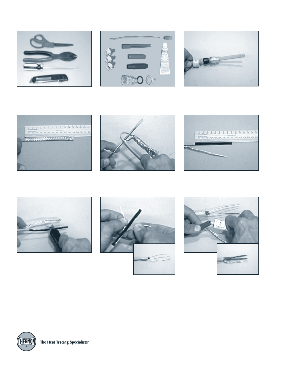
Tools Required for Installation
Scissors, crimper/cutter, flat-blade screw-
driver, and utility knife
Kit Contents
User supplied junction box must be rated
Type 4X (water-tight) and approved for use
in ordinary locations.
Step 2:
Cut overjacket back a distance of
5" (120 mm).
Step 3:
Separate braid strands at
overjacket and pull cable back through
opening in braid.
Step 4:
Cut insulating jacket of cable back
3.5" (90 mm). Wind braid into a pigtail.
Step 5:
Skive outer matrix material from
conductors with a utility knife.
Step 6:
Peel ex-
posed wires back
from center ma-
trix and cut cen-
ter matrix away,
leaving bare conductors. Twist end of bus
wires before inserting into boot to avoid
contact with ground wire.
Step 7:
Squeeze
RTV into the sili-
cone rubber
boot and slide
over cable end.
Verify bus wires do not contact ground
wire.
Power Connection
Step 1:
Slide the junction box fitting cap,
strain relief disk, grommet, and then gland
fitting body onto the power end of cable.