Self-regulating, Completing the installation, Temperature control – Thermon FLX User Manual
Page 5
FLX
TM
Self-Regulating
4
Completing the Installation . . .
1. Begin final cable attachment by securing the end-of-circuit
termination kit and working back toward the power supply.
• Flexible heating cables are to be installed using attachment
tape. Circumferential bands of tape should be installed at
12” (30 cm) intervals to keep the cable in proper contact
with the pipe. Refer to Table 2 below to calculate the num-
ber of rolls of attachment tape required based on the pipe
diameter
1
.
• If applicable, refer to installation details provided with the
project drawings or contact Thermon for additional infor-
mation regarding installation.
2. In addition to the circumferential tape requirements, a
continuous covering of aluminum foil tape may be required
when:
• Spray or foam urethane
2
thermal insulation is applied.
• Heat tracing nonmetallic piping.
• Design requirements dictate the use of aluminum tape to
improve heat transfer.
3. Complete splice connections (if required) in accordance
with the installation instructions provided with the splice kit.
4. Install power connection kit in accordance to the detailed
installation instructions provided with the kit.
5. Before making power connections, repeat the megger test
with at least a 500 Vdc megohmmeter (megger) between
the heating cable bus wires and the heating cable metallic
braid. IEEE 515.1 recommends that the test voltage for
polymer insulated heating cables be 2500 Vdc. The mini-
mum acceptable level for the megger reading for any
polymer-insulated heat tracing cable is 20 megohms.
(Record 2 on Cable Testing Report)
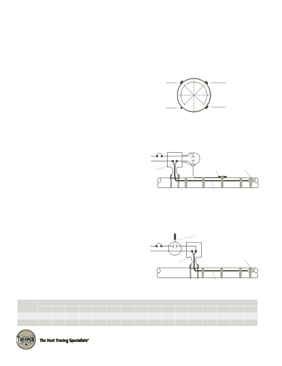
Heating Cable vs. Sensor Location
Temperature Control . . .
1. When a line sensing controller is specified, the sensor should
be placed at least 90° around the circumference from the
heating cable, or at least 2" (5 cm) from the cable.
Tape
Length
Pipe Diameter in Inches
½"-1"
1¼"
1½"
2"
3"
4"
6"
8"
10"
12"
14"
16"
18"
20"
24"
30"
36 yd
130'
115'
110'
95'
75'
65'
50'
40'
35'
30'
26'
23'
21'
19'
16'
13'
60 yd
215'
195'
180'
160'
125'
105'
80'
65'
55'
50'
43'
38'
35'
31'
27'
22'
Heating Cable
(Typical)
Temperature
Sensor
Table 2: Attachment Tape (Value Represents Approximate Linear Pipe Length Allowance Per Roll)
Ambient Sensing Thermostat
End Termination
Power Connection
L1
L2/N
Ambient Sensing Control Connection
Temperature Sensor
End Termination
Power Connection
L1
L2/N
Heating Cable
Pipewall Sensing Control Connection
Heating Cable
3. When using an ambient sensing temperature controller, the
mounting location should be representative of the coldest
region, and the sensing element should not be exposed to
direct sunlight or any additional heat source.
Notes . . .
1. Table 2 assumes circumferential bands every 12” (30 cm) along the length of the piping.
2. Verify exposure temperature of heating cable versus curing temperature of insulation.
2. For pipewall sensing thermostatic control, the heating circuit
is to be connected in series with the control contacts as
shown in illustration below. The pipewall sensing thermostat
may require more than one support point.
90°
Optional Third
Heating Cable
Optional Second
Heating Cable