Installation procedures – Thermon FAK-9 User Manual
Page 3
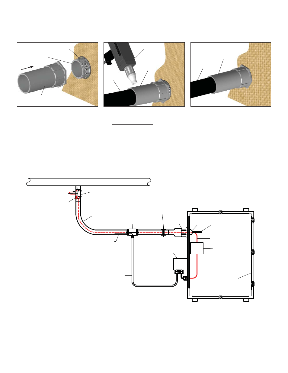
1.
Insert Flange Nut into bulkhead hole and engage
Flange Assembly as shown. Tighten fi rmly by hand.
If further tightening is desired, use suitable spanner
wrench ensuring not to over-tighten as Flange Nut
can be broken.
INSTALLATION PROCEDURES
2
3.
Completed FAK-9 installation.
Heat Shrink
Sealed Tubing
Tubing Bundle
FAK-9
1
Flange Nut
(from back side)
FAK-9
1
Flange
O-Ring
FAK-9
1
Heat Shrink
and Flange Assembly
Enclosure or
shelter wall
Heat Gun
Tubing
Bundle
Heat Shrink
2.
It is recommended that the tubing, heat trace
(where included) and other connections be made
before completing this step. Heat until heat shrink
seal is conformed and sealed to the tube bundle
outer jacket and tubing.
Note . . .
1) Typical - To be used in conjunction with FAK-9, FAK-9S, FAK-9L, and FAK-9XL kits.
Instrument Enclosure
(Typical)
Capilary or RTD Lead Wire
(Shielded and/or Armored, Typically)
Process Stream
Heat Trace
Tubing Bundle
T’Stat or RTD Sensor
FAK-4T
(Optional)
FAK-9
FAK-7
Heat Trace
Power Connection
Thermostat / Controller
(Typical / Optional)
Heat Trace
End Termination
(Typical)
Analyzer Probe
or Hand Valve
(Typically Field Insulated)
Tube to Instrument /
Analyzer Connection
Secure Tubing Bundle
Within 18” of Enclosure
(Typical Minimum)
Typical TubeTrace Installation Overview with Thermon Electric Heat Trace and FAK-9 Bulkhead Entry Heat Shrink . .
.