Terminator, Ecm-p-wp, Installation procedures – Thermon ECM-P-WP User Manual
Page 4: Wiring details
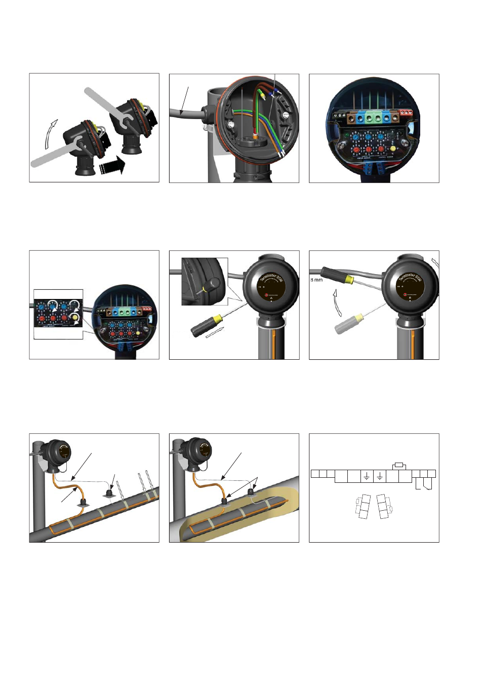
Wiring Details
Connection (1 or 2 Heating Cables)
11.
Install electronic control module and
complete system wiring. Terminal set
screws shall be tightened to a torque
value of 1,4 Nm (12,4 lb-in). See
wiring details. Set modules electronic
control and/or control limiter at desired
setpoints.
L
L
N
N
C
NO
NC
Comm. Port
Alarm Relay
Main supply
Heater output
B
B
A
A
B
B
RTD
Limiter Sensor
RTD
Controller Sensor
GND
1
2
12.
Use the rotary switches for settling
Control and Limit Temperature, (Celsius
or Fahrenheit) and Auto or Manual reset
(Control switches on Type "C", Limiter
switches on Type "L" and both on Type "CL").
1725
II 2 GD Ex eb mb [ib]ib I
IC T4, Ex tb I
IIC T135°C
S
IRA 12A
TEX5239X
IP66
-60°C ≤
Ta ≤ + 55
°C
IECEx SI
R 12.0103X Ex eb mb [ib]ib I
IC T4, Ex tb I
IIC T135°C
PN 27673
D
o n
ot o
pen w
hile energized. See i
nsta
llat
ion
in
st
ru
ct
io
n
s.
Te
rm
inator EC
M
Fo
r
us
e
as
an
ad
just
able e
lectronic contr
ol m
od
ule
1725
II 2 GD Ex eb mb [ib
]ib IIC T4
, Ex tb III
C T135°C
S
IRA 12A
TEX5239X
IP66
-60°C ≤
Ta ≤ + 5
5
°C
IECEx SI
R 12.0103X Ex eb mb [ib]ib I
IC T4, Ex tb I
IIC T135°C
PN 27673
D
o n
ot o
pen w
hile energized. See i
nsta
llat
ion
in
st
ru
ct
io
n
s.
Te
rm
inator EC
M
Fo
r
us
e
as
an
ad
just
able e
lectronic contr
ol m
od
ule
1725 II 2 GD Ex eb mb [ib]ib IIC T4, Ex tb IIIC T135°C
SIRA 12ATEX5239X
IP66
-60
°C ≤ Ta ≤ + 55°C
IECEx SIR 12.0103X Ex eb mb [ib]ib IIC T4, Ex tb IIIC T135°C
PN 27673
D
o n
ot o
pen
while
energized. See installa
tion
in
str
uc
tio
ns
.
Te
rm
inator EC
M
Fo
r u
se
as
an
adj
ustable
electronic c
ontro
l m
od
ule
Power Cable
Terminator
TM
ECM-P-WP
INSTALLATION PROCEDURES
16.
Install IEK insulation entry kit to seal
heating cable and RTD lead wire
penetrations through insulation cladding.
15.
Slide IEK insulation entry kit onto RTD
lead wire. Fix RTD lead wire and sensor
to pipe.
14.
Use screwdriver to ratchet on junction box
lid. Lid will rotate 30 degrees. To remove
lid, repeat steps 13 and 14 but in the
opposite direction.
13.
Install junction box lid and twist hand
tight. Insert screwdriver into ratchet slots
located on side of junction box base.
10.
Install power cable.
9.
Install M25 power gland (order separately)
and M25 blind plug.
RTD Lead Wire
Heat
Trace
IEK
Insulation Entry
RTD Lead Wire
IEK
Insulation Entries