Terminator, Zp-r-xp, Installation procedures – Thermon ZP-R-XP User Manual
Page 4
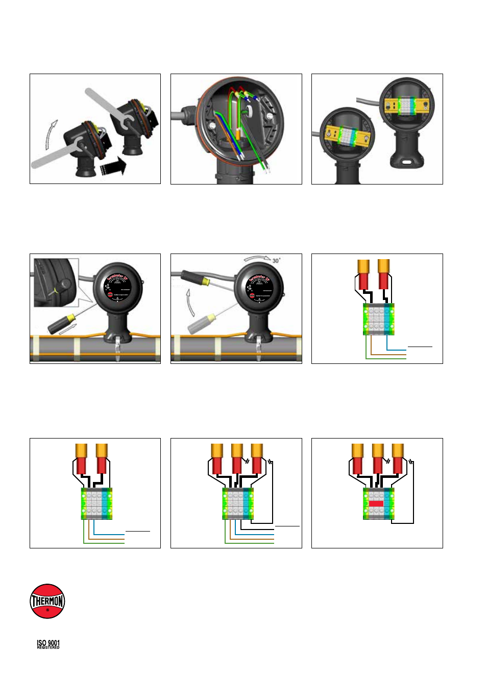
Power Supply
N
L1
PE
Wiring Details: Single Phase Circuit
Heat Tracing
Listed Heat Tracing Cable System 137M
Ordinary & Hazardous Locations
Class I, Division 2, Groups A, B, C & D
Class II, Division 2, Groups F & G, Class III
Class I, Zone 1, AEx e II T4-T6; Ex e II T4-T6
0539 II 2 G & D Ex e II T4-T6
IEC Ex UL 05.0003 Ex e II T4-T6
Listed Heat Tracing Cable System 137M
Ordinary & Hazardous Locations
Class I, Division 2, Groups A, B, C & D
Class II, Division 2, Groups F & G, Class III
Class I, Zone 1, AEx e II T4-T6; Ex e II T4-T6
0539 II 2 G & D Ex e II T4-T6
IEC Ex UL 05.0003 Ex e II T4-T6
10.
Remove M25 dust cap. Install M25
power gland (order separately)
a n d M 2 5 b l i n d p l u g . F o r
in-line splice, T-splice, or end
termination, install additional M25 blind
plug (order M25-B-EXE separately)
instead of M25 power gland.
Specifications and information are subject to change without notice. Form PN50860U-0114
THERMON . . . The Heat Tracing Specialists
®
www.thermon.com
Corporate Headquarters
100 Thermon Dr.
•
PO Box 609
San Marcos, TX 78667-0609
•
USA
Phone: +1 512-396-5801
European Headquarters
Boezemweg 25
•
PO Box 205
2640 AE Pijnacker
•
The Netherlands
Phone: +31 (0) 15-36 15 370
For the Thermon office nearest you
visit us at . . .
www.thermon.com
Terminator
TM
ZP-R-XP
INSTALLATION PROCEDURES
11.
Install power cable.
12.
Install terminal block and complete
system wiring. Terminal set screws shall
be tightened to a torque value of 1.4 Nm
(12.4 lb-in). See below for wiring details.
13.
Install junction box lid and twist hand
tight. Insert screwdriver into ratchet slots
located on side of junction box base.
14.
Use screwdriver to ratchet on junction
box lid. Lid will rotate 30 degrees. To
remove lid, repeat steps 13 and 14 but
in the opposite direction.
Power Supply
L2
L1
PE
Wiring Details: Phase - Phase Circuit
Heat Tracing
Power Supply
L3
L2
L1
PE
Heat Tracing
Wiring Details: 3-Phase Circuit (Power Side)
Wiring Details: 3-Phase Circuit (End or "Star" Side)
Note: Install separately supplied bridge on
terminal L1, L2 and L3.
#1
#2
#3
Heat Tracing
#1
#2
#3