Teo NT1B-300 Rack User Manual
Page 4
Tone Commander NT1B-300 Rack Installation Instructions
Page 4
13-280113 Rev. B
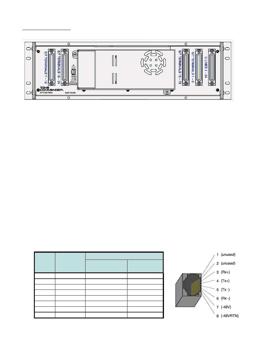
Cable Connections
Back Panel Connectors
All rack S/T and U ribbon connectors are female; male connectors are required on the cable
ends.
U lnterface
Connect each U interface pair from the network interface block into the appropriate position on the 50-pin U
interface connector on the rack rear panel. See Table 2 for connector pinouts. The rack uses self-locking
connectors; to remove a cable, use a small tool to press in the tabs on the ends of the connector.
S/T Interface
The S/T interface for each terminal can be connected one of two ways:
1. Modular jacks on the front of the NT1B-300TC units – for terminal equipment or patch panel connection
via an 8-position modular phone cord. Connecting cords must be Category 3 or higher with T568 A or
T568 B wiring. See Table 1 and the figure below for jack pinout.
Two parallel-wired jacks are provided on each NT1, for two terminals connected in a multipoint
arrangement.
2. 50-pin ribbon connectors on the rack back panel – for terminal equipment connection via a punch-down
block. See Table 2 for connector pinouts.
Connect the terminal wall jacks to 4-pair cables as shown in Table 1. Punch down the cables to the cross-
connect blocks in the order shown in Table 1. Note that pairs 1-2 and 3-6 for T568A jacks are reversed
from T568B jacks.
Wire Color
Pin #
Signal
T568 A
T568 B
*
(AT&T)
5
Tx-
WHT-BLU
WHT-BLU
4
Tx+
BLU
BLU
1
unused
WHT-GRN
WHT-ORN
2
unused
GRN
ORN
3
Rx+
WHT-ORN
WHT-GRN
6
Rx-
ORN
GRN
7
-48V
WHT-BRN
WHT-BRN
8
-48VRTN
BRN
BRN
Table 1 – Modular Jack Pinout