Tecfluid DFD-2 User Manual
Page 3
3
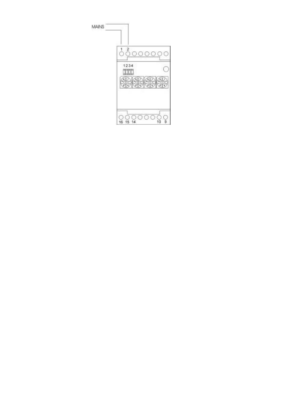
2.1 Mains connection
The mains supply voltage is connected to terminals 1 and 2. The mains voltage is indicated on
the label at the side of terminals 1 & 2.
2.2 Input connection
The DFD is designed to be able to work with three basic types of inputs. The different types are
selected by means of jumpers inside the instrument.
2.2.1 Pick-up Input
For the input from turbine flowmeters which use magnetic inductive pick-ups to detect the
movement of the turbine blades, the wiring must be made as following:
DFD Terminal No. Pick-up Terminal No.
14 shield 1 shield
15 live 2 live
16 live 3 live
"live" means the two ends of the pick-up coil.
The input cables must not be installed close to mains cables as these can induce
errors due to electrical interferences.
2.2.2 Electrical contact or open collector input
For connecting inputs from reed switches etc., as one can find for example in COVOL
counters or pulse generators with an open collector output (NPN transistor), the wiring must
be made as following:
DFD Terminal No. COVOL Terminal No. NPN Open Collector
14 shield 1 shield Emitter
15 no connection
16 live 2 live Collector
The shield is connected to one end of the reed switch and the live to the other end.
2.2.3 TTL input
For connecting inputs from electronic equipment with a TTL (5 V pulse) output the wiring
must be made as following:
DFD Terminal No. TTL Signal
14 shield Common
15 no connection
16 live Live