Tecfluid MT-02 User Manual
Page 2
2
Cod.:E-MI-2151001I Rev.: 2
1
INSTALLATION
1.1
Mounting
The MT-02 control instrument is housed in a DIN 96 x 96 type plastic case for mounting in a
front panel of an electrical control panel via a 90 x 90 mm +0.5mm/-0mm square hole. The electrical
control panel should have a minimum depth of 190 mm behind the front panel to take the MT-02.
IMPORTANT : In order to comply with the electrical safety requirements as per IEC 1010-1, the
installation of the equipment must take into account the following:
-The equipment must be installed in the front panel of an electrical mounting cabinet, leaving
only the front of the equipment accessible to the operator.
-A mains switch must be provided to disconnect the equipment. This switch must be marked as
the disconnecting device for the equipment and be within easy reach of the operator.
-The mains supply must have an earth line.
1.2
Mains
Connection
The connection of the equipment is via plug-in connectors, polarized to avoid mistakes when
plugged in. The connectors have screw terminals, as per VDE norms, to accept 1.5 mm
2
cable.
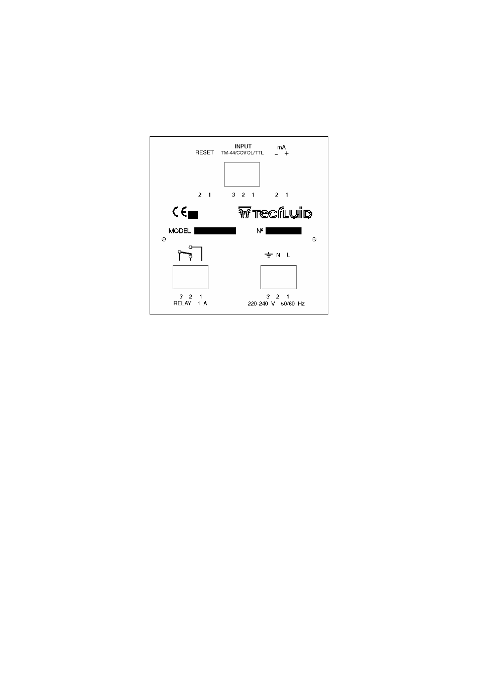
When we refer to the positions of the connectors, it is looking at the back of the MT-02.
The connector for the mains power supply is situated on the bottom right-hand side, in which the
power supply (voltage indicated below the connector) must be connected to terminals Nº1 and Nº2.
Terminal Nº3 should be connected to a good earth. The MT-02 has a
Φ 5 x 20 mm mains fuse inside.
The nominal rating of this fuse depends on the mains voltage.
1.3
Relay
Connection
The connector for the Relay is marked "RELAY 1A" (situated on the bottom left-hand side). The
common contact of the relay is terminal Nº3. The normally open contact (with the relay disactivated) is
terminal Nº1 and the normally closed contact is terminal Nº2. There are no provisions for protection of
the relay contacts inside the MT-02, neither fuse nor over-voltage protection (such as may be needed
with inductive loads), and these must be provided externally as required.