Tecfluid LT-AMM User Manual
Page 3
3
Figure 3
Figure 4
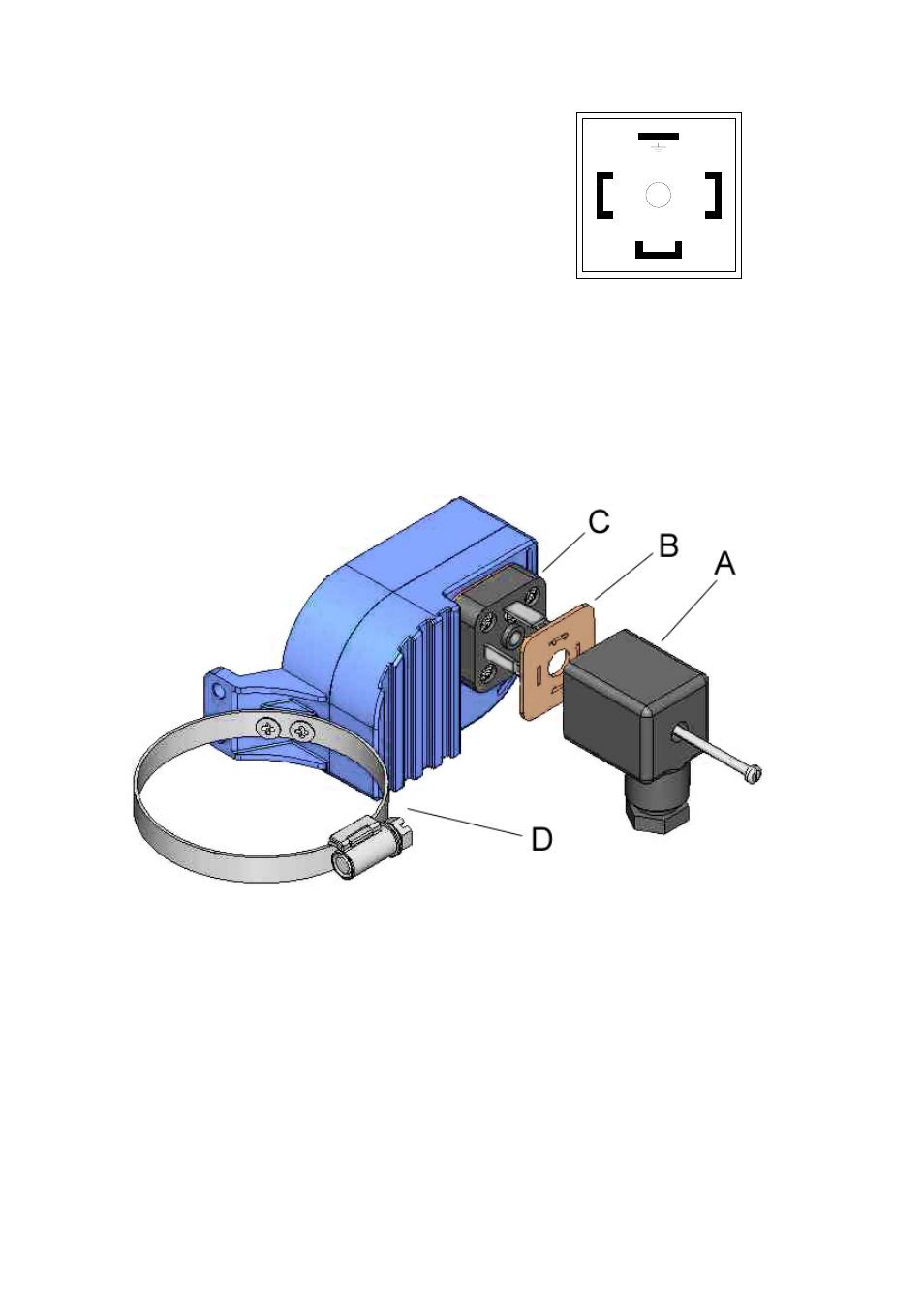
MOUNTING
Once the electrical connection has been made and the cable gland has been tightened, mount the
female connector (A) on the male base (C), placing the seal (B) between the two pieces.
To fix the level switch in its position on the level, completely unscrew the hose band (D) and open
it. With the hose band open situate the level switch on the float tube and close the hose band
over the tube.
Situate the level switch at the required height and tighten the hose band.
In the female connector (A):
Terminal 1: Common
Terminal 2: NO
Terminal 3: NC
Earth terminal: Earth
Terminal 2 is the normally open contact when the float is
below the level switch.
3
1
2
MAINTENANCE (figure of the following page)
Place the limit switch in its normal working position (top figure) and move a magnet in the center of
the hose band (D) as if it was the float. The magnet should be in a vertical position with the North
pole upwards.
The micro-switch lever (1) has a roller that runs on the cam (3).
To check the operation and correct possible misalignments, do the following:
First open the limit switch housing by removing the four M4 x 25 DIN 7985 screws.
Check that the magnet assembly (2) is firmly fixed to the shaft by the screw (5).
Position the screw (5) as in the drawing (against the stop in a clockwise direction). Position the
cam (3) as in the drawing and tighten the screw (4). In this position the lever roller should be at
about 1 mm from the screw head (4).
If a multimeter with resistance measurement is available, connect it to terminals 1 & 2 of the
connector base.