Tecfluid TR2420 User Manual
Page 5
5
If this setup must to be changed, one may proceed in two different ways as follows:
a) Directly with the instrument.
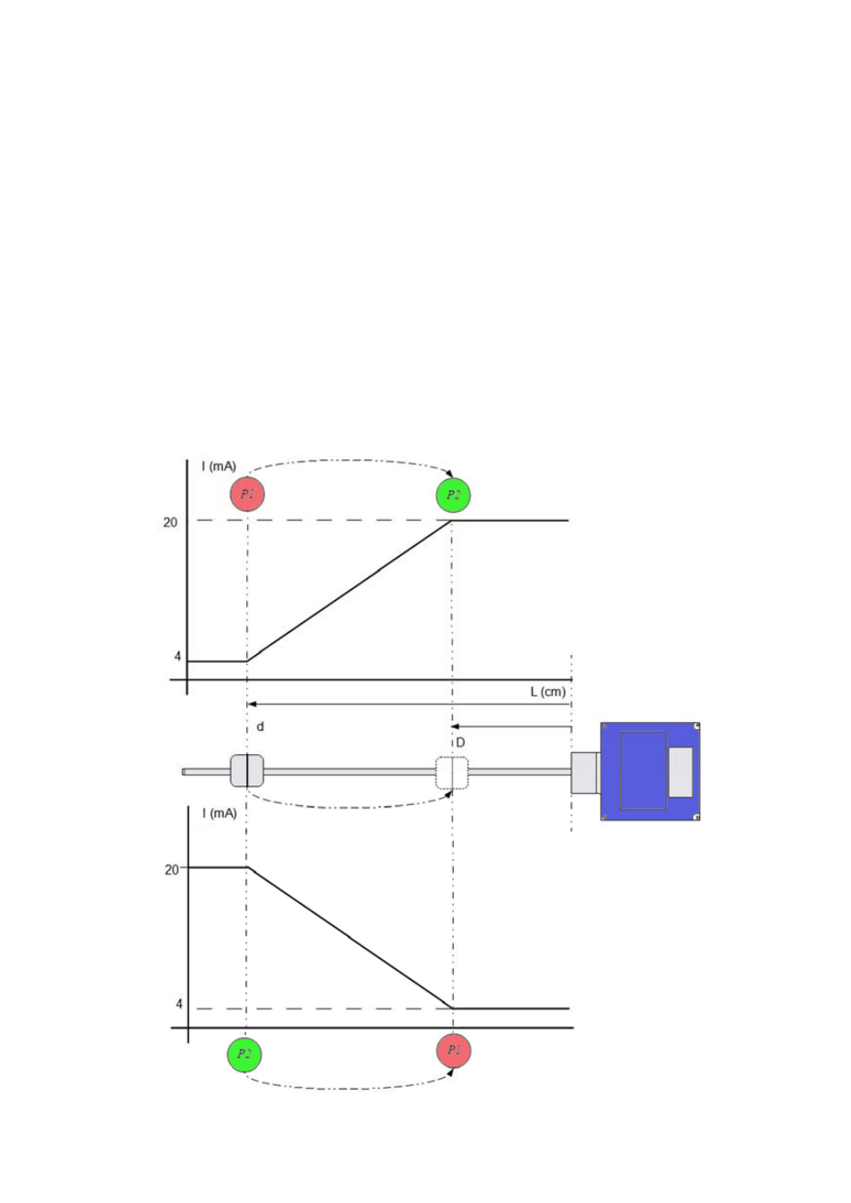
When opening the box cover of the transmitter, 2 push buttons (P1 and P2) and a LED
indicator (L1) can be seen, as shown in page 4.
P1 is the 4 mA programming push button. Likewise P2 is the 20 mA programming push
button.
The push buttons are protected by a pulse time. A short press, less than two seconds, will
not program the instrument.
With the transmitter powered and the write protect jumper placed (page 4), move
the float to the point where you want to transmit 4 mA. Press P1 until the red LED flashes.
Move the float to the point where you want to transmit 20 mA. Press P2 until the green
LED flashes.
Check the operation with a multimeter.
- AMD For 2000 Series (4 pages)
- AMO For 6000 Series (4 pages)
- AMR For 6000 Series (4 pages)
- AMM For 6000 Series (8 pages)
- LT-AMD (4 pages)
- TR420 (8 pages)
- AD Series (4 pages)
- TH6 For M21 Series (12 pages)
- TH5 For DP Series (12 pages)
- AMM For DP Series (8 pages)
- FLOMAT Series (12 pages)
- FLOMID-MX (20 pages)
- XT5D (24 pages)
- MX4H (24 pages)
- FLOMID Series (8 pages)
- MX4 For FLOMAT Series (56 pages)
- LC Series (4 pages)
- LC40 Series (8 pages)
- LC-40 ADF (4 pages)
- MX4 For FLOMID Series (64 pages)
- LD61 (8 pages)
- LD60 (8 pages)
- LD61N (8 pages)
- LD61R (12 pages)
- LP Series (12 pages)
- LT-APR (4 pages)
- LTL-AMM (4 pages)
- LTL-APR (4 pages)
- LTL-ADF (4 pages)
- VH35 AISI-316 (4 pages)
- MC01 4-20 mA input (12 pages)
- LU Series (28 pages)
- MT-02 (9 pages)
- MT03L (32 pages)
- MT03F (40 pages)
- CH420L (8 pages)
- CH420R (12 pages)
- CH420P (12 pages)
- CIP (4 pages)
- CIP II (8 pages)
- DFD-2 E (8 pages)
- APTM44 (6 pages)
- CI-420 (8 pages)