Ld-61 – Tecfluid LD61 User Manual
Page 7
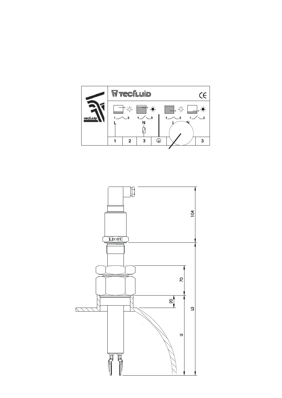
ACCESSORIES
An accessory that permits changing the length of the LD61 which penetrates in the tank is avail-
able. This permits adjustment of the detection level.
7
The cable gland should be situated on the lower side of the connector. If it is necessary, the
position of the connector can be changed by 90º or 180º. To do this, open the connector and
rotate. This operation must be done with the power disconnected
OPERATION TEST
The operation of the installation can be checked by placing a magnet in the zone shown in the
following figure. This magnet will change the output to the opposite state. In this way the correct
installation of the instrument can be checked without having to change the level in the tank. At the
same time, the bi-colour LED will indicate the change of state of the output.
Nº 00000
Test zone
24..250 Vac
350 mA
IP65
max
min
LD-61
- AMD For 2000 Series (4 pages)
- AMO For 6000 Series (4 pages)
- AMR For 6000 Series (4 pages)
- AMM For 6000 Series (8 pages)
- LT-AMD (4 pages)
- TR420 (8 pages)
- AD Series (4 pages)
- TH6 For M21 Series (12 pages)
- TH5 For DP Series (12 pages)
- AMM For DP Series (8 pages)
- FLOMAT Series (12 pages)
- FLOMID-MX (20 pages)
- XT5D (24 pages)
- MX4H (24 pages)
- FLOMID Series (8 pages)
- MX4 For FLOMAT Series (56 pages)
- LC Series (4 pages)
- LC40 Series (8 pages)
- LC-40 ADF (4 pages)
- MX4 For FLOMID Series (64 pages)
- LD60 (8 pages)
- LD61N (8 pages)
- LD61R (12 pages)
- LP Series (12 pages)
- TR2420 (12 pages)
- LT-APR (4 pages)
- LTL-AMM (4 pages)
- LTL-APR (4 pages)
- LTL-ADF (4 pages)
- VH35 AISI-316 (4 pages)
- MC01 4-20 mA input (12 pages)
- LU Series (28 pages)
- MT-02 (9 pages)
- MT03L (32 pages)
- MT03F (40 pages)
- CH420L (8 pages)
- CH420R (12 pages)
- CH420P (12 pages)
- CIP (4 pages)
- CIP II (8 pages)
- DFD-2 E (8 pages)
- APTM44 (6 pages)
- CI-420 (8 pages)