Tecfluid AMD For DP Series User Manual
Page 6
LIMIT SWITCH AMM
1 INTRODUCTION
The AMM limit switch can be used to generate an alarm or an operation when the flow rate
or the level that the instrument is measuring reaches a preset value on the scale plate.
It consists of a micro-switch driven by a cam mounted on the indicating needle.
An instrument can be equipped with one or two micro-switches, depending on the number
of points to be detected.
2 SWITCHING
POINT
ADJUSTMENT
To gain access to the limit switch inside the indicator housing, remove the front cover held
by four M5 x 16 DIN 912 screws, using a 4 mm Allen key. After that, remove the scale
plate sliding it to the left by the guide until it be free.
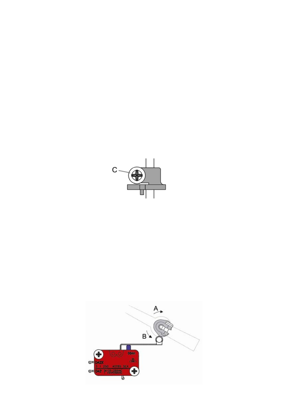
To adjust the switching point, loosen slightly the cam’s grub screw (C) and turn the cam on
the shaft until the required switching point is achieved.
Cam shown acting on
the micro-switch
lever.
To turn the cam on the shaft, do not hold the shaft by the indicating needle, as this may
move the needle on the shaft. The shaft should be held directly.
For the SC BD, SC DES, DP BD, DP DES SM and LP series, if the cam is turned in the “A”
direction, the acting point will move away from the zero point of the scale. If the cam is
turned in the “B” direction, the acting point will move towards the zero point of the scale.
For the SC ED, SC DAB, DP ED and DP DAB series, if the cam is turned in the “A”
direction, the acting point will move towards to the zero point of the scale. If the cam is
turned in the “B” direction, the acting point will move away from the zero point of the scale.
Once the cam is in its position making sure that the cam rests on the follower of the micro-
switch lever, and the grub screw (C) has been tightened, the correct working of the limit
switch should be verified by turning the indicating needle shaft and checking the switching
at the required point.
6
Screw: DIN7981 B-2.2 x 9.5