Tecfluid TR420 User Manual
Page 5
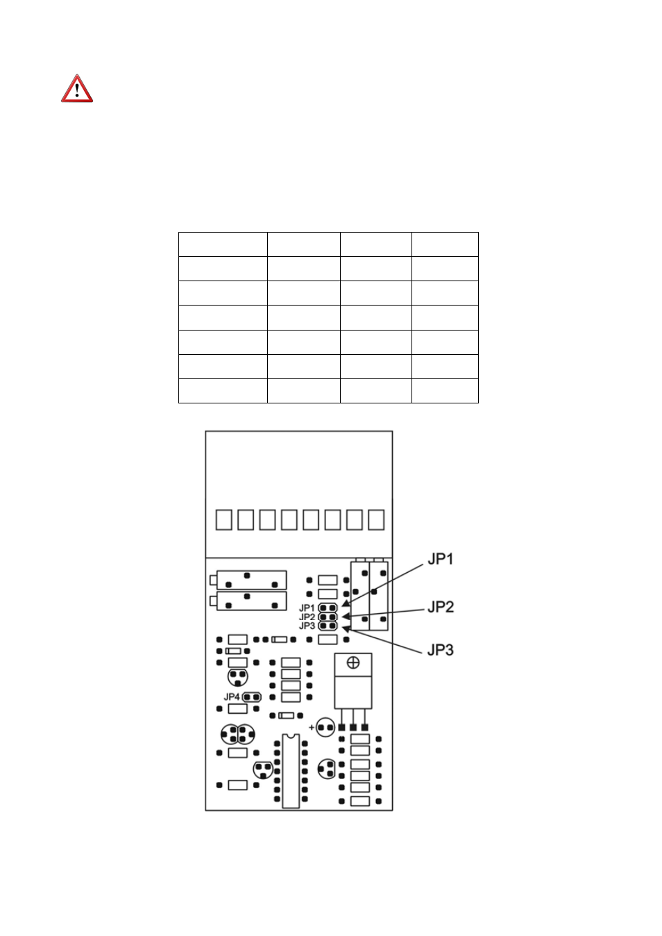
There is a fourth jumper lower down on the printed circuit. It must not be removed as it is only
used for factory adjustments.
The different output modes are selected by means of jumpers on headers inside the
converter.
Before opening the converter the power supply must be disconnected.
In order to open the converter to change the output mode, first remove the transparent top
cover, then press outwards the sides of the plastic case to free the clips in the sides of the
terminal blocks and slide the terminal blocks out together with the printed circuits. It is not
necessary to slide the printed circuits completely out of the case, as the jumpers are just
below the terminal block.
The position of the jumpers is as follows:
5
JP1
JP2
JP3
4 - 20 mA
X
0 - 20 mA
1 - 5 V
X
X
X
0 - 5 V
X
X
2 - 10 V
X
X
0 - 10 V
X
- AMD For 2000 Series (4 pages)
- AMO For 6000 Series (4 pages)
- AMR For 6000 Series (4 pages)
- AMM For 6000 Series (8 pages)
- LT-AMD (4 pages)
- AD Series (4 pages)
- TH6 For M21 Series (12 pages)
- TH5 For DP Series (12 pages)
- AMM For DP Series (8 pages)
- FLOMAT Series (12 pages)
- FLOMID-MX (20 pages)
- XT5D (24 pages)
- MX4H (24 pages)
- FLOMID Series (8 pages)
- MX4 For FLOMAT Series (56 pages)
- LC Series (4 pages)
- LC40 Series (8 pages)
- LC-40 ADF (4 pages)
- MX4 For FLOMID Series (64 pages)
- LD61 (8 pages)
- LD60 (8 pages)
- LD61N (8 pages)
- LD61R (12 pages)
- LP Series (12 pages)
- TR2420 (12 pages)
- LT-APR (4 pages)
- LTL-AMM (4 pages)
- LTL-APR (4 pages)
- LTL-ADF (4 pages)
- VH35 AISI-316 (4 pages)
- MC01 4-20 mA input (12 pages)
- LU Series (28 pages)
- MT-02 (9 pages)
- MT03L (32 pages)
- MT03F (40 pages)
- CH420L (8 pages)
- CH420R (12 pages)
- CH420P (12 pages)
- CIP (4 pages)
- CIP II (8 pages)
- DFD-2 E (8 pages)
- APTM44 (6 pages)
- CI-420 (8 pages)