Mounting, Maintenance – Tecfluid AMM For 6000 Series User Manual
Page 5
5
4 MAINTENANCE
(figure of the following page)
The micro-switch (1) has a roller that runs on the cam (3).
To check the operation and correct possible misalignments, do the following steps:
Open the limit switch housing by removing the four M4 x 25 DIN 7985 screws.
Check that the magnet assembly (2) is firmly fixed to the shaft by the screw (5).
Position the screw (5) as in the drawing (against the stop in a clockwise direction).
Position the cam (3) as in the drawing and tighten the screw (4).
If a multimeter with resistance measurement is available, connect it to terminals 1 & 2 of
the connector. Move the cam (3) slowly in both directions over the whole of its travel. The
multimeter must change from open circuit to short circuit in one direction and vice versa in
the other, when the roller is half way up the eccentric zone of the cam.
When a multimeter is not available, the above can be done by hearing the “click” when the
micro-switch changes over.
Note: If due to bad handling of the micro-switch lever, the operation is not correct, the
micro-switch lever (1) should be bent slightly until correct operation is obtained.
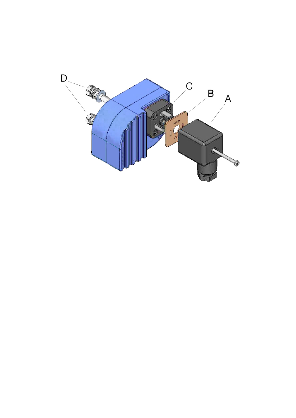
3 MOUNTING
Once the electrical connection has been made and the cable gland has been tightened,
mount the female connector (A) on the male base (C), placing the seal (B) between the
two pieces.
To fix the flow rate detector in a chosen flow rate position, completely screw the nuts (D).