Figure 5. dip switch settings – Tecfluid LTDR Series User Manual
Page 7
7
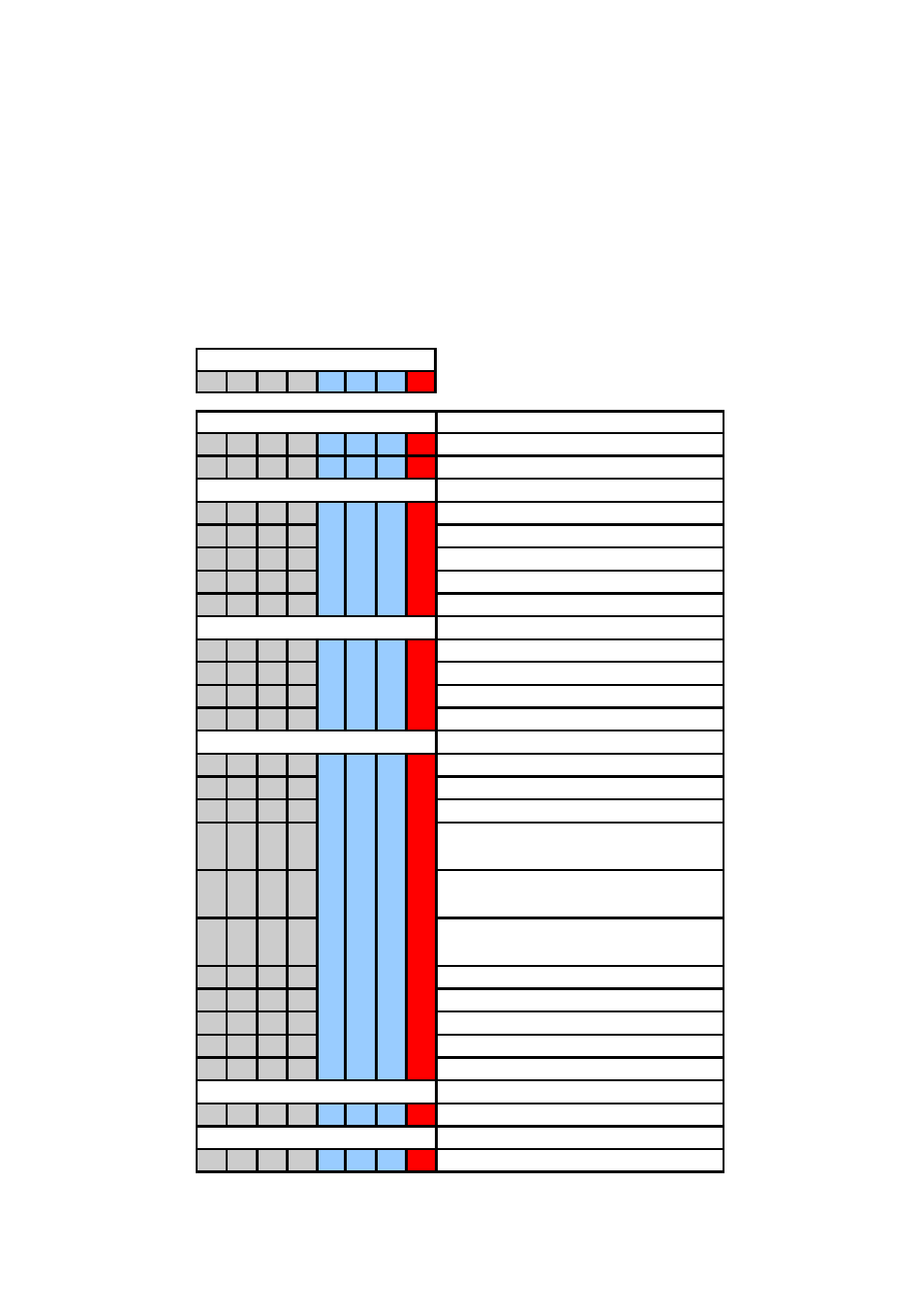
red: indicates DIP switch position 8 which switches between measuring and
configuration mode. Only when DIP switch position 8 is on/1, LTDR can be
configured; configuration mode is indicated by the LED blinking alternately green and
red.
When DIP switch position 8 is off/0, LTDR is in measuring mode; indicated by the
LED blinking green.
It is only possible to enter the configuration mode when DIP switch positions 1 to 7
are off/0 before setting DIP switch position 8 to on/1; otherwise the LED is blinking red
to indicate an error
blue: indicates the DIP positions through which groups of functions are selected, e.g.
all functions related to the analog current output or the switching output
DIP SWITCH SETTINGS
DESCRIPTION
0
0
0
0
0
0
0
0 measuring
mode
0
0
0
0
0
0
0
1 configuration
mode
FUNCTION GROUP 1
ANALOG CURRENT OUTPUT
0
0
0
1
0
0
1
1
lower range value [4mA]; span 0%
0
0
1
0
upper range value [20mA]; span 100%
0
1
0
0
response time 0,5s (default)
0
1
0
1 response
time
2s
0
1
1
0 response
time
5s
FUNCTION GROUP 2
SWITCHING OUTPUT
0
0
1
0
0
1
0
1
lower threshold
0
0
1
1 upper
threshold
0
1
0
0 NC
0
1
0
1 NO
FUNCTION GROUP 3
DISTURBANCE SIGNAL SUPPRESSION
0
0
0
1
0
1
1
perform disturbance signal scan
0
0
1
0
disturbance signal scan: do not utilize
0
0
1
1
disturbance signal scan: utilize (default)
0
1
0
0
upper dead band: short (default)
single rod probe 30mm1
coaxial probe 0mm1
0
1
0
1
upper dead band: medium
single rod probe 190mm1
coaxial probe 160mm1
0
1
1
0
upper dead band: long
single rod probe 390mm1
coaxial probe 360mm1
1
0
0
0
amplitude threshold: low (default)
1
0
0
1
amplitude threshold: medium
1
0
1
0
amplitude threshold: high
1
1
0
0 coaxial
probe
1
1
0
1
Single rod probe
FUNCTION GROUP 4
RESET
0
0
0
1
1
0
0
1
reset to delivery configuration
FUNCTION GROUP 5
MEASURE PROBE LENGTH
0
0
0
1
1
0
1
1 measure
probe
length
1
DIP SWITCH POSITION
1
2
3
4
5
6
7
8
Figure 5. DIP switch settings
1
Always measured from the referente point: sealing surface of the connection thread. See figure 10