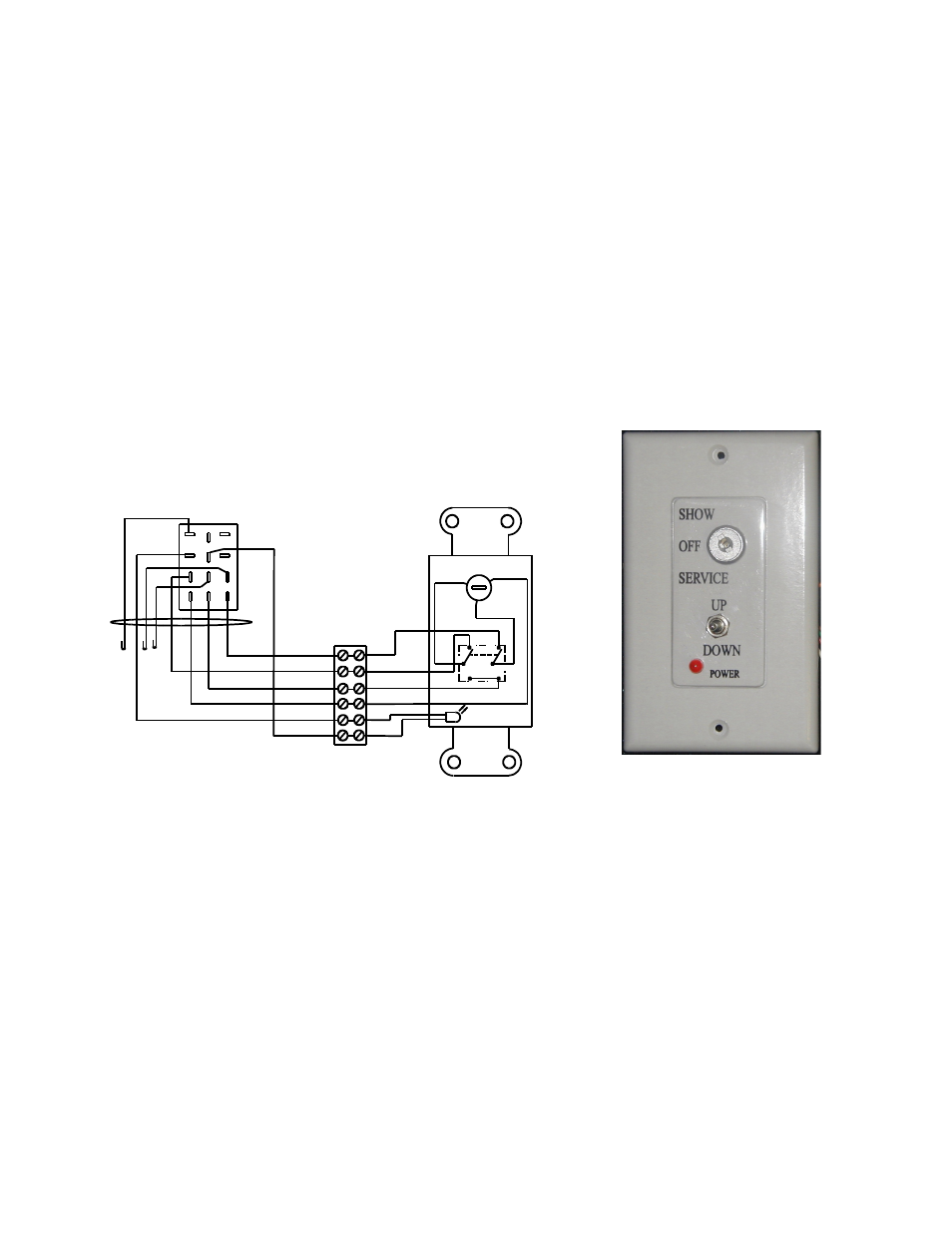
Wall plate controller, Figure 8 wall plate controller wiring diagram, Figure 9 wall plate controller – SVS 7HSE 110V User Manual
Page 10: Rp2 (connects to rj2)
1. Make sure that the area below the Lift is clear and that all cable are clear of the Lift.
2. Apply power to the Lift by plugging it into an AC Outlet.
a. How to use the Wall Plate Controller
1. To lower the Lift to the Show position, turn the key switch to the Show position and press the toggle
switch down. The lift will lower as long as you hold the toggle switch down, the lift will stop when the
rear scissor roller compresses the Show Position microswitch.
2. To lower the Lift to the Service position, turn the key switch to the Service position and press the toggle
switch down. The Lift will lower as long as you hold the toggle switch down, the Lift will stop when the
rear scissor roller compresses the Down Limit microswitch. The Service position bypasses the Show
Position microswitch.
3. To raise the lift press the toggle switch up. The Lift will rise until the Up Limit microswitches are
compressed. The Lift will rise as long as you hold the toggle switch up. The Lift can be raised with the
key switch in either the Show or Service positions.
4. The Off position on the key switch disables the Lift.
5. The Power light on the Wall Plate Controller only comes on when the Lift is raising or lowering (Lift
motor turning), not when power is applied to the Lift.
Important: The toggles switch on the Wall Plate Controller must be pressed to raise or lower the Lift, releasing
the toggle switch stops the Lift. This is designed as a safety feature. The key switch is an extra precaution, when
the key is removed, the Lift is secure.
b. Connecting a Touch Screen Controller (External Controller)
The simplest external controller connections are to use the White wire (pin 1) as the common and the Brown
wire (pin 3) for down to Show position and the Red wire (pin 2) for up. For this and other wiring options please
refer to the external controller wiring diagrams in the Appendix. Also:
1. Program a release of relays to stop the Lift on up and down positions
2. Program a time out after the normal runtime, 2 seconds max. (SVS Lifts raise/lower at 1-inch/second.)
3. Program an exclusive lockout on up and down so that both cannot be activated at the same time. (Note:
SVS Lifts have a lockout function that disables the Lift when it receives a up and down command at the
same time. Removing one of the two commands releases the lockout condition.)
SVS 7HSE Lift Installation Instructions
Page 10 of 16
Figure 8 Wall Plate Controller Wiring Diagram
VIEW FROM BACK
(24vac)
+
-
(SERVICE)
C
2
1
GRN BRN
UP
PUR
BLK
BLU
WHT
MOTOR
POWER ON
WHT
DOWN
SHOW-OFF-SERVICE
RP2 (CONNECTS TO RJ2)
YEL
(SHOW)
RED
WHT
ORN
BLK
GRN
RED
WHT
BLK
ORN
GRN
BRN
BRN
3
2
1
4
5
6
9
8
7
12
11
10
WALL PLATE CONTROLLER
Figure 9 Wall Plate
Controller