Connectors pin-out, Figure 2 sdb connector pin-out – Sundance SMT373 User Manual
Page 8
Version 1.8
Page 8 of 15
SMT373 User Manual
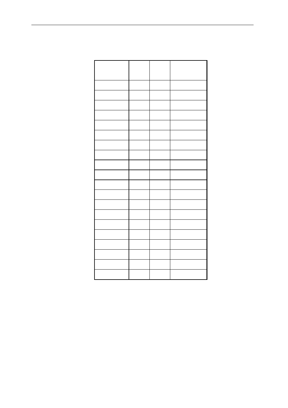
Connectors Pin-out
Function Pin Pin Function
GND 2 1 CLK
GND 4 3 D0
GND 6 5 D1
GND 8 7 D2
GND 10 9
D3
GND 12
11 D4
GND 14
13 D5
GND 16
15 D6
GND 18
17 D7
GND 20
19 D8
GND 22
21 D9
GND 24
23 D10
GND 26
25 D11
GND 28
27 D12
GND 30
29 D13
GND 32
31 D14
GND 34
33 D15
DIR2 36
35
USERDEF0
DIR0 38
37 WEN
DIR1 40
39
USERDEF1
Figure 2 SDB connector pin-out
DIR0 sets the direction of the line USERDEF0, DIR1 of the line USERDEF1 and
DIR2 of lines D0 to D15, CLKIN and WEN. Each transceiver acts as a driver when its
direction pin is high and as a receiver when its direction pin is low.
See also other documents in the category Sundance Equipment:
- SMT107 (16 pages)
- SMT6035 v.2.2 (39 pages)
- SMT6012 v.4.6 (22 pages)
- FC100 (12 pages)
- FC108 v.1.1 (10 pages)
- SMT6065 v.4.0 (45 pages)
- FFT v.2.1 (19 pages)
- SMT111 (18 pages)
- SMT118LT (10 pages)
- SMT118 (20 pages)
- SMT123-SHB (13 pages)
- SMT128 (15 pages)
- SMT145 (18 pages)
- SMT148 (35 pages)
- SMT130 v.1.0 (46 pages)
- SMT148FX (48 pages)
- SMT310Q (55 pages)
- PARS (70 pages)
- SMT166-FMC (52 pages)
- SMT166 (44 pages)
- SMT300Q v.1.6 (61 pages)
- SMT310 v.1.6 (50 pages)
- SMT317 (24 pages)
- SMT326v2 (24 pages)
- SMT338 (19 pages)
- SMT349 (32 pages)
- SMT339 v.1.3 (27 pages)
- SMT338-VP (22 pages)
- SMT358 (25 pages)
- SMT351T (37 pages)
- SMT351 (25 pages)
- SMT350 (45 pages)
- SMT362 (30 pages)
- SMT365G (23 pages)
- SMT364 (37 pages)
- SMT368 (24 pages)
- SMT370v3 (46 pages)
- SMT377 (22 pages)
- SMT381 2007 (31 pages)
- SMT381-VP (81 pages)
- SMT387 (42 pages)
- SMT391 (18 pages)
- SMT384 (47 pages)
- SMT390-VP (55 pages)