Operation, Model 740, Labeling the unit for clarity – Studio Technologies 740 User Manual
Page 15: Mic/line inputs
Model 740 User Guide
Issue 3, May 2004
Studio Technologies, Inc.
Page 15
Model 740
3. Using an appropriate adapter cable,
connect a high-input-impedance audio
level meter directly across the refer-
ence tone direct output. Ensure that
this meter connection does not remove
the normal load! The level meter must
be a precision device that’s intended
for audio use—a general-purpose volt-
meter is not adequate!
4. While carefully observing the level
meter, adjust the trim pot to give the
desired output level.
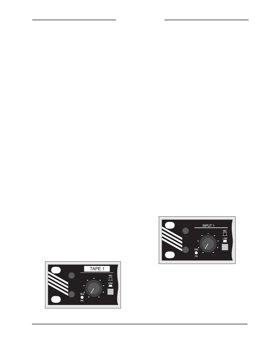
Labeling the Unit for Clarity
Once the Model 740 has been installed,
installation-specific labeling of the front
panel may want to be performed. This ad-
ditional clarity can greatly assist operators
in correctly using the unit. For example,
instead of the first mic/line input channel
having the factory-standard text INPUT
1, it could reflect its exact function, such
as TAPE 1. The unit’s front-panel graph-
ics were specifically created to simplify
the task of adding custom labels. Under
each section heading text is a horizontal
green line, which, besides looking pretty
sharp, is intended to serve as a “guide”
for adding installation-specific labels. The
distance from the guide line to the top of
the unit was specifically designed to allow
¼-inch-high label material to fit correctly.
For a great look it is recommended that
Brother® P-Touch ¼-inch (6 mm) labels
be created. Selecting tape material that
prints white text on a black background
works out perfectly for the Model 740. The
Brother label cassette number TX-3151,
white on black, is appropriate for use with
some of their printers.
Operation
While the Model 740 Audio Mixer is quite
simple to operate, there are nuances in
its design that make a detailed discussion
worthwhile. We’ll start with the individual
sections that make up the Model 740,
then we’ll review how the sections work
together to become your audio “master
control.”
Mic/Line Inputs
Six identical input channels are provided,
each being compatible with a microphone
or line-level signal. The following provides
a detailed description of one of the mic/
line inputs:
Detail of front panel showing one mic/line input
channel
Detail of front panel showing installation-
specific label
Input Sensitivity
The input circuitry is compatible with a
wide range of signal levels and is protect-
ed from overload. The mic/line button is
used to select the sensitivity of the input.