Model 740, External monitor inputs, Main output—general information – Studio Technologies 740 User Manual
Page 11
Model 740 User Guide
Issue 3, May 2004
Studio Technologies, Inc.
Page 11
Model 740
The output utilizes a 3-pin male XLR-type
connector for interconnection. Prepare the
mating connector (female) so that pin 2
is signal high (+ or hot), pin 3 is low (– or
cold), and pin 1 is shield. Whether this
output is wired via a patch bay will depend
on the specific installation. But at least
having a “mult” of the main output on a
patch point is probably a good idea.
While balanced operation is generally
preferred, unbalanced operation is not
a problem for the output circuitry. To con-
nect to an unbalanced load prepare the
mating connector (female) so that pin 2 is
high (+ or hot), and both pins 1 and 3 are
shield. For optimal unbalanced operation,
it is important to connect both pins 1 and
3 together directly on the connector that
mates with the Model 740, not at the other
end of the cable.
External Monitor Inputs
Two external audio signals can be con-
nected, allowing them to be monitored
independently of the activity on the main
audio bus. It is intended that the external
monitor inputs be connected to outputs
associated with devices such as off-air,
microwave, or satellite receivers, or other
specialized devices such as PC-based
video editing systems. The inputs are
Main Output—General
Information
The Model 740 contains one output that
is associated with the main audio bus.
It is electronically balanced, capacitor
coupled, and has a nominal level of
+4 dBu. The output circuitry is capable of
driving balanced or unbalanced loads of
600 ohms or greater. Note, however, that
as the load impedance approaches 600
ohms the output level will drop slightly. A
0.5 dB difference in output level can be
expected as the load impedance changes
from 10 k ohms to 600 ohms. This loading
situation also applies to the monitor and
reference tone direct outputs as well.
Note that the main output is intended only
for connection to devices located within
a broadcast vehicle or dedicated indoor
facility. While the output circuitry is robust
and sonically excellent, it’s not intended
for direct exposure to the extreme condi-
tions that can occur in the nasty “outside
world.” This limitation is normally not an
issue as the main output will typically be
connected to the input of a distribution
amplifier. Should the main output need
to be connected directly to a vehicle’s I/O
panel, at a minimum a 1:1 isolation trans-
former should be placed in its path.
Detail of back panel showing external monitor
input connectors
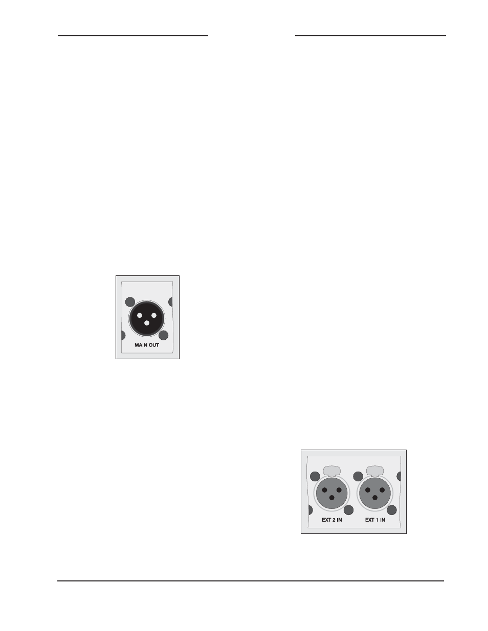
Detail of back panel showing main output
connector